Eureka AIR delivers breakthrough ideas for toughest innovation challenges, trusted by R&D personnel around the world.

Energy-saving drying box

A technology of drying oven and drying warehouse, which is applied in drying solid materials, drying safety system, drying gas arrangement, etc., can solve problems such as inability to effectively control heating temperature, poor drying efficiency of drying oven, and high energy consumption of electric heating resistance wires. , to achieve the effect of prolonging the heat exchange time, good heat dissipation effect and good insulation effect

Inactive Publication Date: 2018-06-26
安徽依诺格实验室设备有限公司
View PDF6 Cites 6 Cited by
  • Summary
  • Abstract
  • Description
  • Claims
  • Application Information

AI Technical Summary

Problems solved by technology

[0003] Most of the existing drying ovens use electric heating resistance wires for heating. The electric heating resistance wires consume a lot of energy, generate low temperatures, and cannot effectively control the heating temperature. The drying efficiency of the drying ovens is not good; During the heating process of the air, the heat cannot be fully utilized, and the energy consumption is large

Method used


Image

  • Energy-saving drying box
  • Energy-saving drying box
  • Energy-saving drying box

Examples


Embodiment Construction

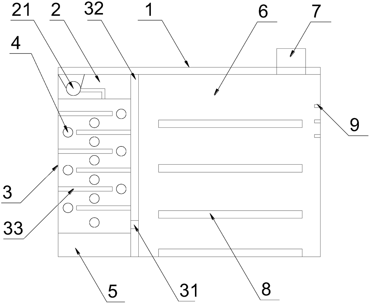
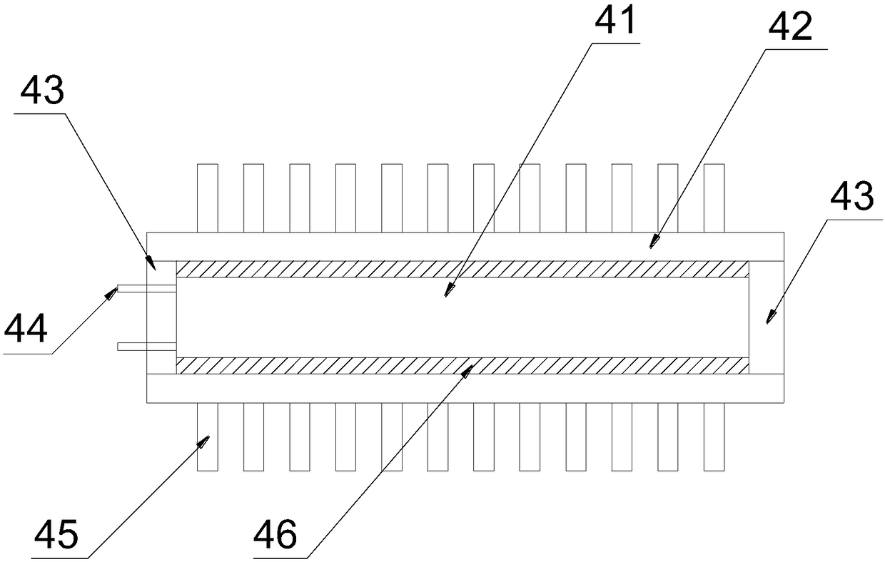
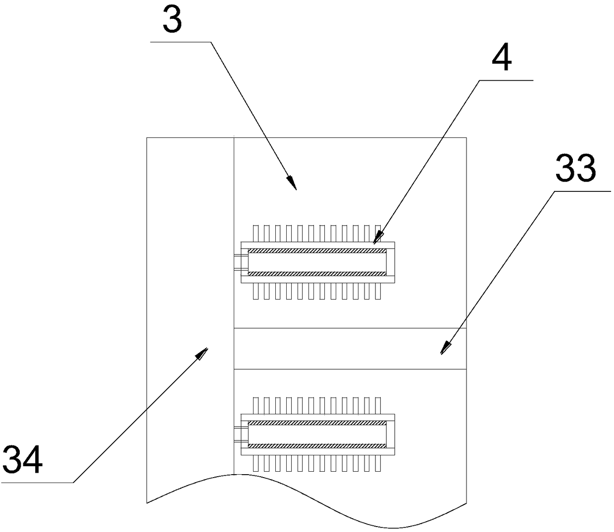
[0021] Such as Figure 1-4 as shown, figure 1 A schematic structural view of an energy-saving drying oven proposed by the present invention figure 2 It is a structural schematic diagram of the heating assembly in the energy-saving drying box proposed by the present invention, image 3 It is a schematic diagram of the partial structure of the drying chamber in the energy-saving drying oven proposed by the present invention, Figure 4 It is a schematic diagram of the outer structure of the energy-saving drying box proposed by the present invention.

[0022] refer to Figure 1-4 An energy-saving drying box proposed by the present invention includes a box body 1, an equipment bin 2, a heating bin 3, a control bin 5 and a drying bin 6; When the door 11 is closed, it forms a sealed structure with the box body 1, and the signal of the display screen 12 and the control panel 13 are connected to the PLC control system installed inside the control compartment 5, and the control com...


PUM


Abstract

The invention discloses an energy-saving drying box. The energy-saving drying box comprises a box body, an equipment bin, a heating bin, a control bin and a drying bin; a box door, a display screen and a control panel are arranged on the outer side of the box body, and the control bin is located at the bottom of the box body; a partition plate is arranged in the box body, the equipment bin, the heating bin and the control bin are located on the left side of the partition plate, the drying bin is located on the right side of the partition plate, a vent hole is formed in the bottom of the partition plate, and the heating bin communicates with the drying bin through the vent hole; the equipment bin is located on the upper portion of the interior of the box body, and the heating bin is locatedbetween the equipment bin and the control bin; baffles are arranged in the heating bin, and the ends of the baffles are fixed to the inner wall of the heating bin and the partition plate; an S-shapedair channel is formed in the heating bin; multiple heating assemblies are arranged in the flowing direction of air in the S-shaped air channel; and multiple rows of storage racks are fixedly installed in the drying bin, an exhaust port is arranged on the top of the drying bin, and a one-way valve is arranged at the exhaust port. According to the energy-saving drying box, the drying effect is good, the heat exchange efficiency is high, the energy utilization rate is increased, energy waste is avoided, and use is safe.

Description

technical field [0001] The invention relates to the field of laboratory equipment, in particular to an energy-saving drying oven. Background technique [0002] The drying box is a common equipment in the laboratory. During the work of the drying box, the electric heating method is used to heat the gas, and the hot air is used to dry and dry the experimental equipment, and it can also provide the temperature environment required for the experiment; [0003] Most of the existing drying ovens use electric heating resistance wires for heating. The electric heating resistance wires consume a lot of energy, generate low temperatures, and cannot effectively control the heating temperature. The drying efficiency of the drying ovens is not good; During the heating process of the air, the heat cannot be fully utilized, and the energy consumption is large. Contents of the invention [0004] In order to solve the technical problems existing in the background technology, the present i...

Claims


Application Information

Patent Timeline
IPC IPC(8): F26B9/10F26B21/00F26B25/00
CPCF26B9/10F26B21/001F26B25/009
Inventor 唐来星陈世勤陆和喜乔满林吴克林
Owner 安徽依诺格实验室设备有限公司
Why Eureka
Eureka Blog
Learn More