Current stabilizer spacing change type non-condensable gas tubular heat exchanger

A technology of shell-and-tube heat exchangers and flow stabilization devices, which is applied in the directions of indirect heat exchangers, heat exchanger types, heat transfer modification, etc., and can solve the problem of vibration and noise of gas-liquid two-phase flow heat exchangers. Unable to achieve the uniformity of the gas phase and liquid phase, and the disturbance of the heat exchange tubes cannot be guaranteed, so as to achieve the effect of reducing the noise level, reducing noise and vibration, and smooth flow

Active Publication Date: 2018-06-26
山东卓奥环保科技股份有限公司
4 Cites 16 Cited by

AI-Extracted Technical Summary

Problems solved by technology

However, the above-mentioned technology does not solve the vibration and noise problems in the gas-liquid two-phase flow heat exchanger, and the above-mentioned solution has a complex structure, and because of the size of the thorns, the disturbance on the entire cross-section in the middle of the heat exchange tube cannot be guaranteed. The overall uniformity of the g...

Method used

The present invention divides the gas-liquid two-phase at all cross-sectional positions of all heat exchange tubes, thereby realizing the contact area of ​​the gas-liquid interface and the segmentation of the gas phase boundary layer and the cooling wall surface on the entire heat exchange tube section Enhanced disturbance greatly reduces noise and vibration, and enhances heat transfer.
The present invention is provided with multi-tube type steady flow device in heat exchange tube, by multi-tube type steady flow device, liquid phase and gas phase in two-phase fluid are separated, and liquid phase is divided into small liquid mass, and gas phase is divided into Small air bubbles inhibit the backflow of the liquid phase, promote the smooth flow of the gas phase, stabilize the flow rate, and have the effect of reducing vibration and noise.
[0046] The main reason is that non-condensable gas is contained in the fluid, so along the flow direction of the fluid, the non-condensable gas still exists and will not condense because of the heat release of the fluid in the heat exchange tube. From the inlet of the heat exchange tube 6 to the middle of the heat exchange tube 6, because the fluid enters the heat exchange tube from the front head 1, the vibration and noise of the fluid in the front part of the heat exchange tube 6 flow relatively less, so the steady flow can be The distance between the devices is set larger, which can not only achieve shock absorption and noise reduction, but also reduce resistance. However, from the middle of the heat exchange tube to the back, because there is a space from the heat exchange tube 6 to the rear head 9, the space changes from small to large, and the change of this section will cause the gas to flow out and accumulate quickly, and the liquid will also quickly The lower part of the item flows out and accumulates, so the space change will cause the accumulated gas phase (air mass) to enter the head from the tube sheet position. Due to the difference in gas (steam) and liquid density, the air mass will move upward quickly when it leaves the connection position, and the original space position of the air mass is changed. The liquid that the air mass pushes away from the wall will also rebound quickly and hit the wall, creating an impact phenomenon. The more discontinuous the gas (steam) liquid phase, the greater the accumulation of air masses and the greater the energy of water hammer. The impact phenomenon will cause large noise vibration and mechanical shock, causing damage to the equipment. Therefore, in order to avoid this phenomenon, the distance between the adjacent flow stabilization devices set at this time is getting shorter and shorter, thereby increasing the density of the flow stabilization device, and continuously increasing the separation of the gas phase and the liquid phase during the fluid delivery process. Thereby minimizing vibration and noise.
[0053] The present invention provides a multi-tube type steady flow device, which is equivalent to adding inner fins in the heat exchange tubes, which strengthens the heat exchange and improves the heat exchange effect.
[0055] Preferably, by setting an insert in the space between the shell 52 and the outermost pipe 51, it is ensured that the pipes ar...

Abstract

The invention provides a tube-shell heat exchanger. The tube-shell heat exchanger comprises a housing, wherein sealing heads are arranged at two ends of the housing; tube plates are arranged at positions where the sealing heads are connected to the housing; heat exchange tubes are connected to the tube plates at two ends; gas phase in gas-liquid two-phase current is insoluble or slightly-soluble gas, namely, gas cannot dissolve in liquid in the heat exchanging process. The tube-shell heat exchanger is characterized in that current stabilizers for absorbing vibration and reducing noise are arranged in the heat exchange tubes; a plurality of current stabilizers are arranged in one heat exchange tube; the spacing between adjacent current stabilizers gradually increases in the flowing direction of the liquid in the heat exchange tubes until reaching some position, and then the spacing between the adjacent current stabilizers gradually decreases from the some position. According to the heatexchanger, the vibration of pipelines can be minimized based on the spacing change of the current stabilizers while the pipelines are subjected to gas-liquid two-phase flowing, and moreover, the noise level is decreased, and meanwhile, the flowing resistance is reduced.

Application Domain

Technology Topic

Image

  • Current stabilizer spacing change type non-condensable gas tubular heat exchanger
  • Current stabilizer spacing change type non-condensable gas tubular heat exchanger
  • Current stabilizer spacing change type non-condensable gas tubular heat exchanger

Examples

  • Experimental program(1)

Example Embodiment

[0041] The specific embodiments of the present invention will be described in detail below in conjunction with the accompanying drawings.
[0042] In this article, if there is no special explanation, when it comes to formulas, "/" means division, and "×" and "*" mean multiplication.
[0043] It should be noted that, unless otherwise specified, the two-phase flow mentioned in the present invention is a gas-liquid two-phase flow, and the gas here is an insoluble or poorly soluble gas, that is, the gas will not dissolve in the liquid during the heat exchange process.
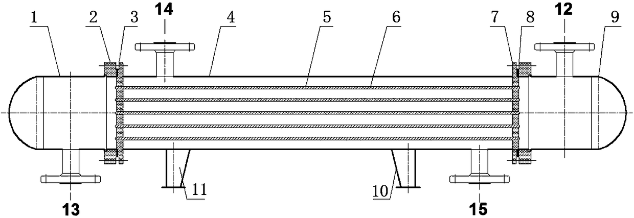
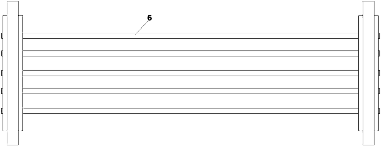
[0044] like figure 1 A shell-and-tube heat exchanger is shown, and the shell-and-tube heat exchanger includes a shell 4, a heat exchange tube 6, a tube-side inlet pipe 12, a tube-side outlet pipe 13, a shell-side inlet connecting pipe 14 and a shell The outlet connecting pipe 15; the heat exchange tube bundle composed of a plurality of parallel heat exchange tubes 6 is connected to the front tube sheet 3 and the rear tube sheet 7; the front end of the front tube sheet 3 is connected to the front head 1, and the rear tube sheet The rear end of 7 is connected to the rear head 9; the tube side inlet pipe 12 is arranged on the back head 9; the tube side outlet pipe 13 is arranged on the front head 1; the shell side inlet connection pipe 14 and the shell-side outlet connecting pipe 15 are both arranged on the shell 4; the two-phase flow fluid enters from the tube-side inlet pipe 12, passes through the heat exchange tube for heat exchange, and exits from the tube-side outlet pipe 13.
[0045] The heat exchange tube 6 is provided with a flow stabilization device 5 for shock absorption and noise reduction, and a plurality of flow stabilization devices 5 are provided in the same heat exchange tube 6, such as Figure 4 As shown, along the flow direction of the fluid in the heat exchange tube 6 (that is, from the inlet of the heat exchange tube to the outlet of the heat exchange tube), the distance between adjacent flow stabilization devices 5 gradually increases first, and then increases to a certain value. A position, and then from a certain position, the spacing of the flow stabilization device gradually decreases.
[0046]The main reason is that the fluid contains non-condensable gas, so along the flow direction of the fluid, the non-condensable gas still exists and will not condense due to the heat release of the fluid in the heat exchange tube. From the inlet of the heat exchange tube 6 to the middle of the heat exchange tube 6, because the fluid enters the heat exchange tube from the front head 1, the vibration and noise of the fluid in the front part of the heat exchange tube 6 flow relatively less, so the steady flow can be The distance between the devices is set larger, which can not only achieve shock absorption and noise reduction, but also reduce resistance. However, from the middle of the heat exchange tube to the back, because there is a space from the heat exchange tube 6 to the rear head 9, the space changes from small to large, and the change of this section will cause the gas to flow out and accumulate quickly, and the liquid will also quickly The lower part of the item flows out and accumulates, so the space change will cause the accumulated gas phase (air mass) to enter the head from the tube sheet position. Due to the difference in gas (steam) and liquid density, the air mass will move upward quickly when it leaves the connection position, and the original space position of the air mass is changed. The liquid that the air mass pushes away from the wall will also rebound quickly and hit the wall, creating an impact phenomenon. The more discontinuous the gas (steam) liquid phase, the greater the accumulation of air masses and the greater the energy of water hammer. The impact phenomenon will cause large noise vibration and mechanical shock, causing damage to the equipment. Therefore, in order to avoid this phenomenon, the distance between the adjacent flow stabilization devices set at this time is getting shorter and shorter, thereby increasing the density of the flow stabilization device, and continuously increasing the separation of the gas phase and the liquid phase during the fluid delivery process. Thereby minimizing vibration and noise.
[0047] Preferably, along the flow direction of the fluid in the heat exchange tubes, the length of the flow stabilizing device 5 gradually decreases to a greater extent.
[0048] Preferably, along the flow direction of the fluid in the heat exchange tube, the length of the flow stabilizing device 5 gradually increases to a larger extent.
[0049] It has been found through experiments that such setting can further reduce the vibration and noise by about 10%, and at the same time reduce the flow resistance by about 5%.
[0050] Preferably, the length of the heat exchange tube is L, and the certain position is a middle position of the length L of the heat exchange tube.
[0051] The structure of the tube bundle type flow stabilization device 5 is shown in image 3. like image 3 As shown, the flow stabilizing device 5 includes a core body and a casing 52, the core body is arranged in the casing 52, the casing is connected and fixed to the inner wall of the heat exchange tube, and the core body is composed of a number of parallel tubes 51 contiguously combined.
[0052] In the present invention, a multi-tube type steady flow device is arranged in the heat exchange tube, and the liquid phase and the gas phase in the two-phase fluid are separated through the multi-tube type steady flow device, the liquid phase is divided into small liquid masses, and the gas phase is divided into small bubbles. Inhibit the backflow of the liquid phase, promote the smooth flow of the gas phase, play a role in stabilizing the flow, and have the effect of reducing vibration and noise.
[0053] In the present invention, by arranging a multi-tube type flow stabilization device, it is equivalent to adding inner fins in the heat exchange tubes, thereby strengthening the heat exchange and improving the heat exchange effect.
[0054] The present invention divides the gas-liquid two-phase at all cross-sectional positions of all heat exchange tubes, thereby realizing the separation of the gas-liquid interface and the gas-phase boundary layer and the contact area of ​​the cooling wall surface on the entire heat exchange tube section, and enhancing the disturbance. The noise and vibration are greatly reduced, and the heat transfer is enhanced.
[0055] Preferably, an insert is provided in the space between the shell 52 and the outermost tube 51 to ensure tight connection between the tubes and to ensure that the tube 51 is fixed in the shell 52 .
[0056] Preferably, adjacent tubes 51 are connected together by welding. They are connected together by welding to ensure a firm connection between the pipes.
[0057] Preferably, small holes are provided between adjacent pipes 51 to achieve penetration. By setting small holes, it can ensure that the adjacent pipes are connected to each other, and the pressure between the pipes can be evened out, so that the fluid in the high-pressure channel flows to the low-pressure channel, and at the same time, the liquid phase and the gas phase can be further separated while the fluid is flowing, which is beneficial Further stabilize the two-phase flow.
[0058] Preferably, along the flow direction of the fluid in the heat exchange tube, a plurality of flow stabilization devices are arranged in the heat exchange tube, and the distance between adjacent flow stabilization devices becomes longer and longer from the inlet of the heat exchange tube to the middle of the heat exchange tube. From the middle of the heat exchange tube to the outlet of the heat exchange tube, the distance between adjacent flow stabilization devices becomes shorter and shorter. That is, the length of the heat exchange tube is L, the distance from the inlet of the heat exchange tube is X, and the distance between adjacent flow stabilization devices is S, S=F 1 (X), S' is the first derivative of S, which meets the following requirements:
[0059] S'>0,0
[0060] S'<0, L/2
[0061] The main reason is that the fluid contains non-condensable gas, so along the flow direction of the fluid, the non-condensable gas still exists and will not condense due to the heat release of the fluid in the heat exchange tube. From the inlet of the heat exchange tube 6 to the middle of the heat exchange tube 6, because the fluid enters the heat exchange tube from the front head 1, the vibration and noise of the fluid in the front part of the heat exchange tube 6 flow relatively less, so the steady flow can be The distance between the devices is set larger, which can not only achieve shock absorption and noise reduction, but also reduce resistance. However, from the middle of the heat exchange tube to the back, because there is a space from the heat exchange tube 6 to the rear head 9, the space changes from small to large, and the change of this section will cause the gas to flow out and accumulate quickly, and the liquid will also quickly The lower part of the item flows out and accumulates, so the space change will cause the accumulated gas phase (air mass) to enter the head from the tube sheet position. Due to the difference in gas (steam) and liquid density, the air mass will move upward quickly when it leaves the connection position, and the original space position of the air mass is changed. The liquid that the air mass pushes away from the wall will also rebound quickly and hit the wall, creating an impact phenomenon. The more discontinuous the gas (steam) liquid phase, the greater the accumulation of air masses and the greater the energy of water hammer. The impact phenomenon will cause large noise vibration and mechanical shock, causing damage to the equipment. Therefore, in order to avoid this phenomenon, the distance between adjacent flow stabilization devices is getting shorter and shorter, so as to continuously separate the gas phase and liquid phase during fluid delivery, thereby reducing vibration and noise to the greatest extent.
[0062] Through experiments, it is found that through the above-mentioned setting, the vibration and noise can be reduced to the greatest extent, and at the same time, the flow resistance of the fluid can be guaranteed to be reduced.
[0063] Further preferably, from the inlet of the heat exchange tube to the middle of the heat exchange tube, the distance between the adjacent flow stabilization devices increases continuously, and from the middle of the heat exchange tube to the outlet of the heat exchange tube, the adjacent The distance between the flow stabilization devices is getting shorter and shorter and the magnitude is increasing. That is, S" is the second derivative of S, which meets the following requirements:
[0064] S">0,0
[0065] S">0, L/2
[0066] It has been found through experiments that such setting can further reduce the vibration and noise by about 10%, and at the same time reduce the flow resistance by about 5%.
[0067] Preferably, the length of each flow stabilizing device remains unchanged.
[0068] Preferably, except for the distance between adjacent flow stabilization devices, other parameters of the flow stabilization devices (such as length, pipe diameter, etc.) remain unchanged.
[0069] As preferably, along the flow direction of the fluid in the heat exchange tube 6, a plurality of flow stabilization devices 5 are arranged in the heat exchange tube 6, and the longer the length of the flow stabilization device 5 is from the entrance of the heat exchange tube 6 to the middle part of the heat exchange tube 6 Shorter and shorter, from the middle of the heat exchange tube 6 to the outlet of the heat exchange tube 6, the length of the flow stabilization device 5 is getting longer and longer. That is, the length of the steady flow device is C, C=F 2 (X), C' is the first derivative of C, which meets the following requirements:
[0070] C'<0,0
[0071] C'>0, L/2
[0072] Further preferably, from the inlet of the heat exchange tube to the middle part of the heat exchange tube, the length of the flow stabilization device becomes shorter and shorter, and the length of the flow stabilization device becomes shorter and shorter from the middle part of the heat exchange tube to the outlet of the heat exchange tube. The longer the amplitude keeps increasing. That is, C" is the second derivative of C, which meets the following requirements:
[0073] C">0,0
[0074] C">0,L/2
[0075] The specific reason is the same as the change of the distance between adjacent flow stabilizing devices.
[0076] Preferably, the distance between adjacent flow stabilizing devices remains unchanged.
[0077] Preferably, except for the length of the flow stabilization device, other parameters of the flow stabilization device (such as adjacent spacing, pipe diameter, etc.) remain unchanged.
[0078] As preferably, along the flow direction of the fluid in the heat exchange tube 6, a plurality of flow stabilization devices are arranged in the heat exchange tube 6, and from the entrance of the heat exchange tube 6 to the middle part of the heat exchange tube 6, different tubes in the flow stabilization device 5 The diameter of 51 is getting bigger and bigger, and the diameters of tubes 51 in different flow stabilization devices 5 are getting smaller and smaller from the middle of the heat exchange tube to the outlet of the heat exchange tube. That is, the pipe diameter of the steady flow device is D, D=F 3 (X), D' is the first derivative of D, which meets the following requirements:
[0079] D'>0,0
[0080] D'<0, L/2
[0081] Preferably, from the inlet of the heat exchange tube to the middle of the heat exchange tube, the diameter of the tube of the flow stabilization device increases continuously, and from the middle of the heat exchange tube to the outlet of the heat exchange tube, the diameter of the tube of the flow stabilization device Smaller and smaller amplitudes keep increasing. which is
[0082] D" is the second derivative of D, which meets the following requirements:
[0083] D">0,0
[0084] D">0, L/2
[0085] The specific reason is the same as the change of the distance between adjacent flow stabilizing devices.
[0086] Preferably, the length of the flow stabilizing device and the distance between adjacent flow stabilizing devices remain unchanged.
[0087] Preferably, except for the pipe diameter of the flow stabilization device, other parameters of the flow stabilization device (eg length, distance between adjacent flow stabilization devices, etc.) remain unchanged.
[0088] Further preferred, such as Figure 4 As shown, the heat exchange tube 6 is provided with a groove inside, and the shell 52 of the flow stabilizing device 5 is arranged in the groove.
[0089] Preferably, the inner wall of the shell 52 is aligned with the inner wall of the heat exchange tube 6 . By aligning, the surface of the inner wall of the heat exchange tube is on the same plane to ensure the smoothness of the surface.
[0090] Preferably, the thickness of the shell 52 is smaller than the depth of the groove, so that grooves can be formed on the inner wall of the heat exchange tube, thereby enhancing heat transfer.
[0091] Further optional, such as Figure 5 As shown, the heat exchange tube 6 is welded in a multi-section structure, and a flow stabilization device 5 is provided at the junction of the multi-section structure. In this way, the manufacture of the heat exchange tube provided with the flow stabilizing device is simplified and the cost is reduced.
[0092]Through analysis and experiments, we know that the distance between the flow stabilization devices should not be too large. If it is too large, the effect of shock and noise reduction will not be good. At the same time, it should not be too small. If it is too small, the resistance will be too large. The outer diameter cannot be too large or too small, which will also lead to poor shock absorption and noise reduction effect or excessive resistance. Therefore, through a large number of experiments, the present invention first satisfies the normal flow resistance (total pressure is below 2.5Mpa, Or when the resistance along the path of a single heat exchange tube is less than or equal to 30Pa/m), the vibration and noise reduction can be optimized, and the best relationship of each parameter has been sorted out.
[0093] The distance between adjacent flow stabilization devices is S, the length of the flow stabilization device is C, the outer diameter of the heat exchange tube is W, and the outer diameter of the tube of the flow stabilization device is D, which meet the following requirements:
[0094] S/C=a-b*LN(W/D); Wherein LN is a logarithmic function, a, b are parameters, wherein 16<8.78;
[0095] Wherein the spacing S of the flow stabilization device is the distance between the opposite ends of the adjacent flow stabilization device; that is, the distance between the tail end of the front flow stabilization device and the front end of the rear flow stabilization device. For details, see Figure 4 logo.
[0096] 34mm
[0097] 7mm
[0098] 14mm
[0099] 50mm
[0100] Preferably, the length L of the heat exchange tube is between 3000-9000 mm. More preferably, between 4500-6000mm.
[0101] More preferably, 40mm
[0102] 9mm
[0103] 18mm
[0104] 55mm
[0105] By optimizing the optimal geometric scale of the above formula, the best effect of shock and noise reduction can be achieved under normal flow resistance conditions.
[0106] Further preferably, with the increase of W/D, a keeps increasing and b keeps decreasing.
[0107] Further preferably, as the volume ratio of the gas phase increases, a decreases continuously and b increases continuously.
[0108] Preferably, the volume ratio of the gaseous phase does not exceed 30%. More preferably not more than 20%. More preferably between 1% and 10%.
[0109] More preferably, a=16.7, b=8.5.
[0110] For other parameters, such as pipe wall, shell wall thickness and other parameters can be set according to normal standards.
[0111] Preferably, the shell-side fluid is water.
[0112] Preferably, the fluid velocity in the tube is 2-4m/s.
[0113] Preferably, the ratio of the length L of the heat exchange tube to the shell diameter of the heat exchanger is 6-10.
[0114] Preferably, the pipe 51 extends along the entire length of the flow stabilizing device 5 . That is, the length of the pipe 51 is equal to the length of the flow stabilizing device 5 .
[0115] Although the present invention has been disclosed above with preferred embodiments, the present invention is not limited thereto. Any person skilled in the art can make various changes and modifications without departing from the spirit and scope of the present invention, so the protection scope of the present invention should be based on the scope defined in the claims.

PUM

no PUM

Description & Claims & Application Information

We can also present the details of the Description, Claims and Application information to help users get a comprehensive understanding of the technical details of the patent, such as background art, summary of invention, brief description of drawings, description of embodiments, and other original content. On the other hand, users can also determine the specific scope of protection of the technology through the list of claims; as well as understand the changes in the life cycle of the technology with the presentation of the patent timeline. Login to view more.

Similar technology patents

Jaw type vibration crusher

InactiveCN101829612AReduce the loss of raw materialsReduce vibrationGrain treatmentsElectric machineryDrive motor
Owner:文山通用机械制造有限责任公司

Classification and recommendation of technical efficacy words

  • Reduce vibration
  • Reduce noise level

Axial-flow fan

InactiveUS20070122271A1Increase amount of airflowReduce noise levelPump componentsStatorsImpellerAirflow
Owner:SANYO DENKI CO LTD
Why Eureka
Try Eureka