Centrifugal fertilization device

A fertilization device and connected technology are applied in the field of centrifugal fertilization devices, which can solve the problems of unfavorable mechanical fertilization, slow fertilization efficiency, and difficulty in discharging fertilizer, and achieve the advantages of improving work efficiency and fertilizing range, improving crushing uniformity, and improving crushing speed. Effect

Inactive Publication Date: 2018-06-29
韦健敏
View PDF2 Cites 3 Cited by
  • Summary
  • Abstract
  • Description
  • Claims
  • Application Information

AI Technical Summary

Problems solved by technology

[0002] There are many small-scale farmlands in southern China, and it is inappropriate and wasteful to use large-scale mechanized equipment, and if agricultural production is carried out in a purely manual manner, the efficiency is relatively low, so there is an urgent need for a method that can adapt to the conditions of small-scale farmlands. Fertilizer
Generally, small-scale farmland mainly uses solid-state chemical fertilizers. Because solid-state chemical fertilizers are convenient for storage and transport

Method used


Image

  • Centrifugal fertilization device
  • Centrifugal fertilization device
  • Centrifugal fertilization device

Examples


Example Embodiment

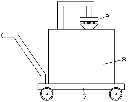
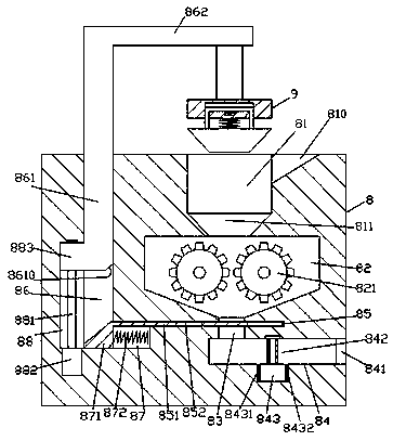
[0021] Such as Figure 1-Figure 6 As shown, a centrifugal fertilization device of the present invention includes a push cart 7 and a fertilizer applicator body 8 mounted on the top of the push cart 7. A feeding trough 81 is provided in the top end of the fertilizer applicator body 8 and the bottom of the feeding trough 81 A conical groove 811 is connected to each other, a chute 810 is provided on the top of the inner wall of the right side of the feeding trough 81, a crushing cavity 82 is connected to the bottom of the conical groove 811, and a rotating crushing assembly 821 is provided in the crushing cavity 82 , The bottom of the crushing cavity 82 is connected with a discharge port 83, the bottom of the discharge port 83 is connected with a centrifugal fertilization cavity 84 extending to the right side, the centrifugal fertilization cavity 84 is provided with a centrifugal fertilization mechanism , The discharging port 83 is provided with a sliding groove 85 extending left ...


PUM


Abstract

The invention discloses a centrifugal fertilization device which comprises a trolley and a fertilization machine body mounted at the top of the trolley; a feeding tank is arranged in the end surface at the top of the fertilization machine body, a conical groove is communicated with and arranged at the bottom of the feeding tank, an oblique groove is formed in the top of an inner wall on the rightside of the feeding tank, a crushing cavity is communicated with and arranged at the bottom of the conical groove, a rotary crushing component is arranged in the crushing chamber, a discharging port is communicated with and arranged in the bottom of the crushing chamber, a centrifugal fertilization chamber formed in a manner of extending rightwards is communicated and formed in the bottom of the discharging port, a centrifugal fertilization mechanism is arranged in the centrifugal fertilization chamber, a slide groove formed in a manner of extending leftwards and rightwards is formed in the discharging port in a penetrating manner, a first guide groove formed in a manner of extending downwards is communicated with and formed in the extending tail end on the left side of the slide groove, alifting slide groove formed in a manner of extending upwards is communicated and formed in the tail end on the left side of the first guide groove, a sliding baffle arranged in a manner of extendingleftwards and rightwards is in sliding fit connection with the inside of the sliding groove. The centrifugal fertilization device disclosed by the invention is simple in structure, convenient to operate, improves the crushing uniformity of agglomerated fertilizers, reduces the fertilizer waste phenomenon and improves the fertilization rate.

Description

technical field [0001] The invention relates to the technical field of agricultural fertilization machinery, in particular to a centrifugal fertilization device. Background technique [0002] There are many small-scale farmlands in southern China, and it is inappropriate and wasteful to use large-scale mechanized equipment, and if agricultural production is carried out in a purely manual manner, the efficiency is relatively low, so there is an urgent need for an Fertilization equipment. Generally, small-scale farmland mainly uses solid-state chemical fertilizers. Because solid-state chemical fertilizers are convenient for storage and transportation, however, solid-state chemical fertilizers often have agglomeration problems in special weather. Serious agglomeration of chemical fertilizers is difficult to break, which is not good for mechanical fertilization. In addition, it is easy to cause Fertilizers are not easy to discharge and cause the blockage of the fertilization po...

Claims


Application Information

Patent Timeline
IPC IPC(8): A01C17/00B02C1/00B02C4/08B02C21/02
CPCA01C17/001A01C17/005B02C1/00B02C4/08B02C21/02
Inventor 韦健敏
Owner 韦健敏
Why Eureka
Try Eureka