MEMS microstructure three-axis excitation device with movable base structure

An excitation device and microstructure technology, applied in the direction of microstructure devices, microstructure technology, etc., can solve problems such as inflexibility, increased error in measurement results, and complicated adjustment process, so as to achieve smooth adjustment process, reduce shear force, The effect of accurate measurements

Inactive Publication Date: 2018-06-29
BOHAI UNIV
View PDF13 Cites 0 Cited by
  • Summary
  • Abstract
  • Description
  • Claims
  • Application Information

AI Technical Summary

Problems solved by technology

[0006] 2. There is no direct connection between the upper connection block and the lower connection block and the sleeve, but are installed in the sleeve in turn by means of clearance fit. If the parallelism error of the two working surfaces of the stacked piezoelectric ceramics is large , there is not enough space to adjust the movable base structure;
[0007] 3. The pressure sensor is installed at the bottom of the lower connecting block. Since the movable base structure adjusts itself, there is a certain inclination between the bottom of the lower connecting block and the working surface of the piezoelectric ceramic, so the pre-tightening force measured by the pressure sensor Or the output force of piezoelectric ceramics is not accurate; in addition, if the movable base structure causes the upper coupling block or the lower coupling block to contact the sleeve after adjustment, the error of the measurement result will further increase;
[0009] 5. In this device, gaskets of different thicknesses are used to change the magnitude of the pre-tightening force applied to the stacked piezoelectric ceramics, which makes the adjustment process complicated and not flexible enough

Method used


Image

  • MEMS microstructure three-axis excitation device with movable base structure
  • MEMS microstructure three-axis excitation device with movable base structure
  • MEMS microstructure three-axis excitation device with movable base structure

Examples


Embodiment Construction

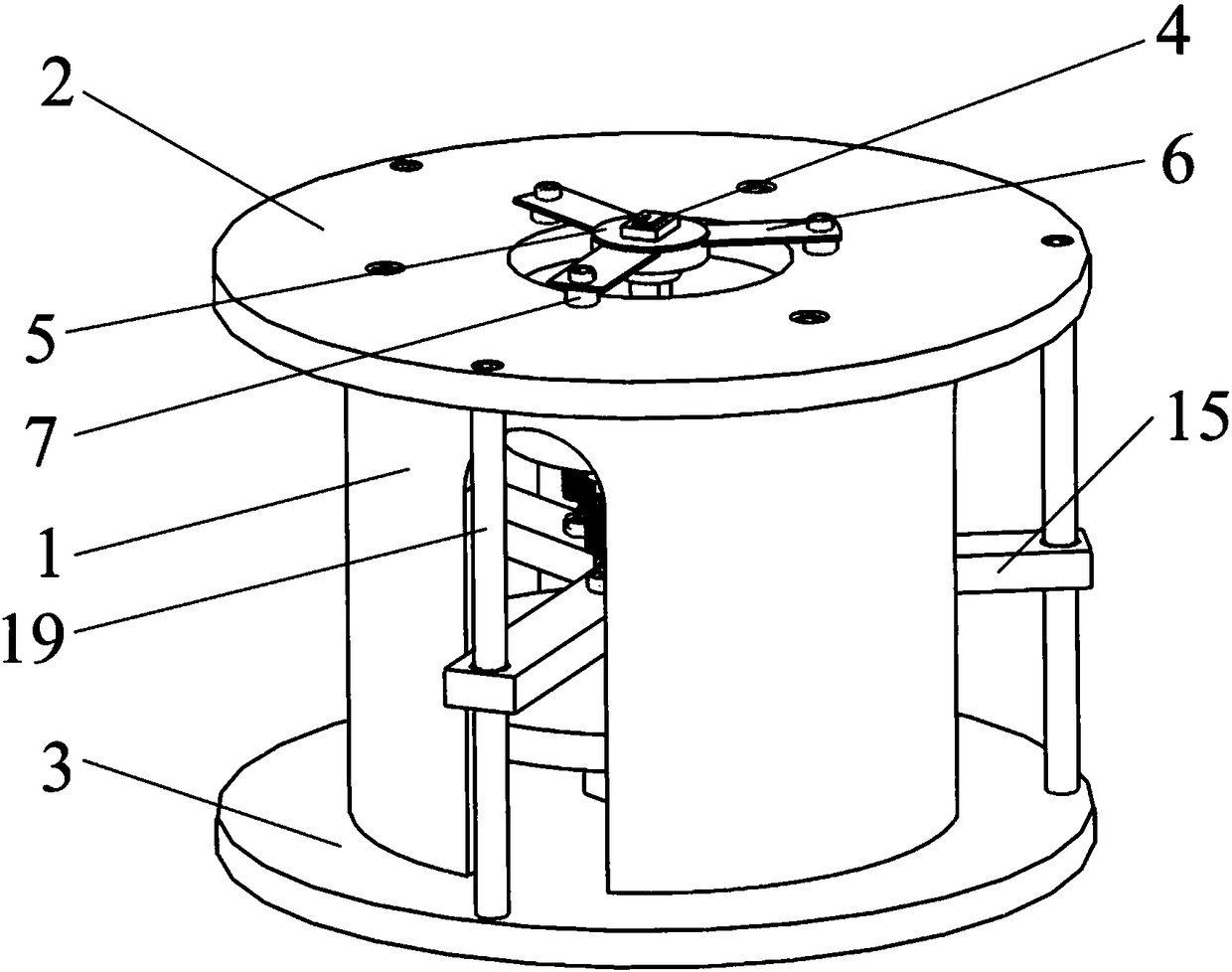
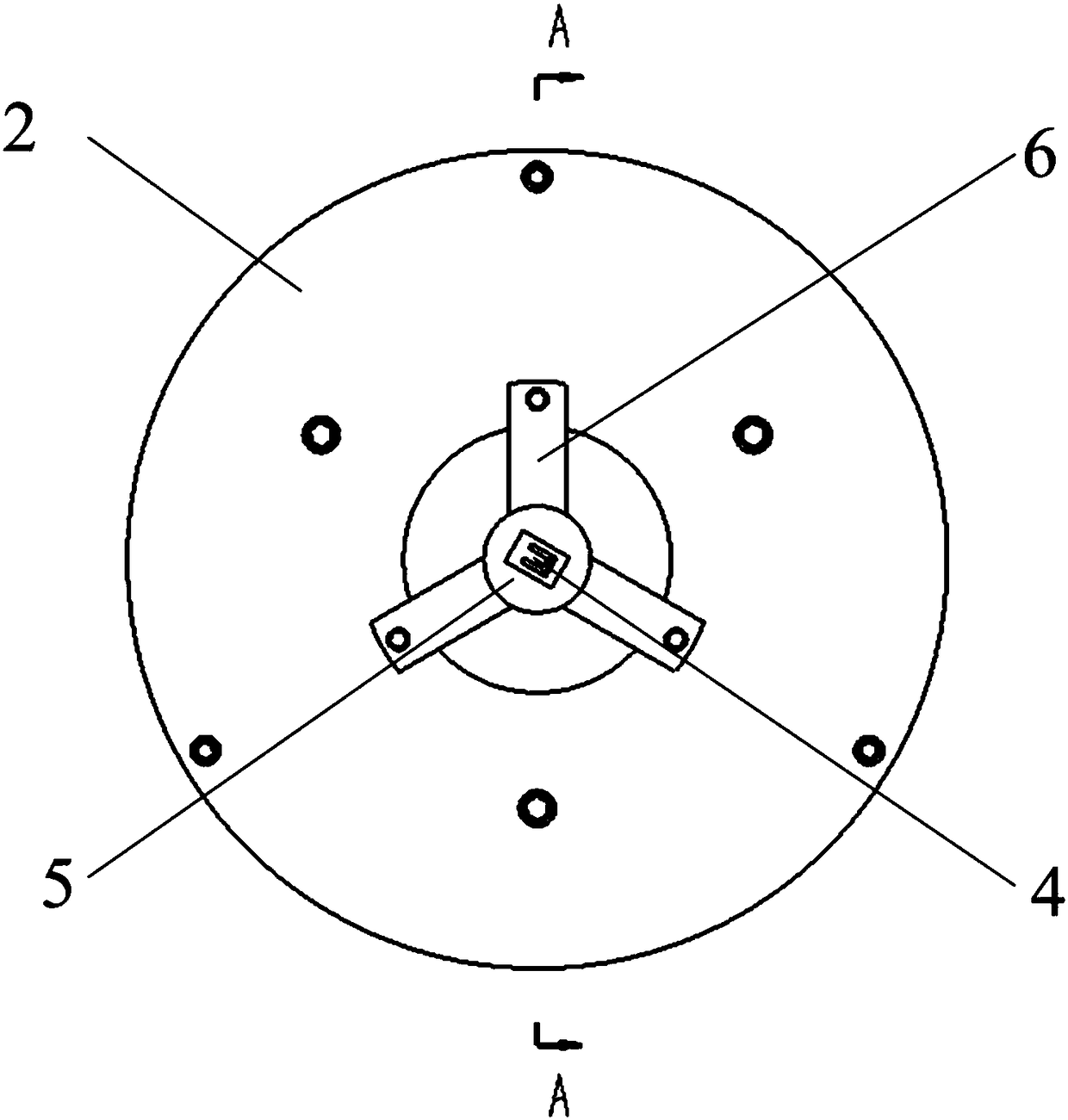
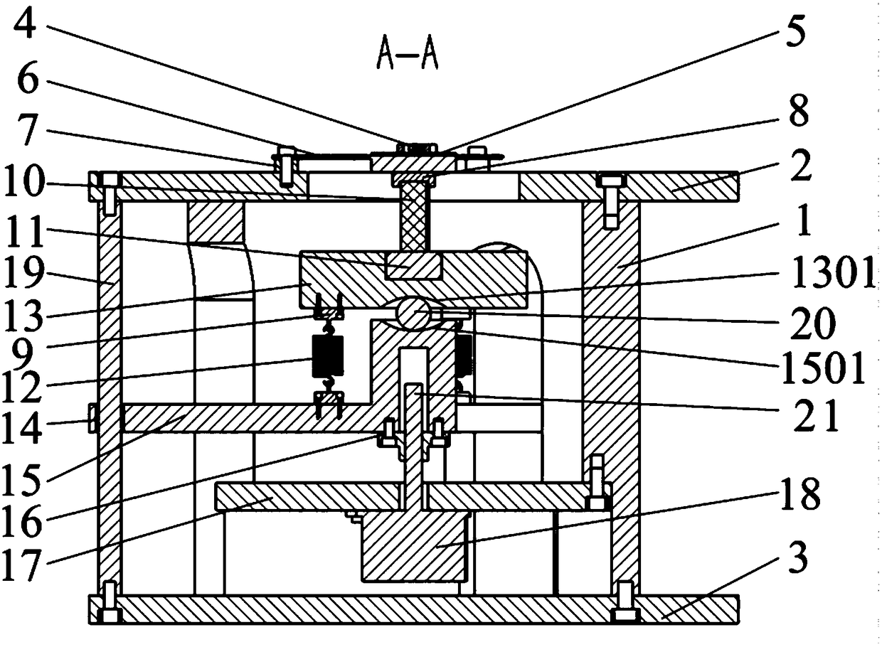
[0037] like Figure 1 to Figure 6 As shown, the present invention relates to a MEMS microstructure three-axis excitation device with a movable base structure, comprising a hollow sleeve 1, in which a stacked piezoelectric ceramic 10, a pressure sensor 11 and The movable base composed of the upper coupling block 13 , the steel ball 20 and the lower coupling block 15 is provided with an elastic support 6 and a MEMS microstructure 4 on the sleeve 1 .

[0038] An annular top plate 2 and a bottom plate 3 with equal outer diameters and larger than the outer diameter of the sleeve are respectively fixed by screws on the top and bottom of the sleeve 1 , and the MEMS microstructure 4 is mounted on the annular top plate 2 through elastic supports 6 . The elastic support member 6 is composed of a cylindrical pressing piece 601 and three radially arranged supporting pieces 602 uniformly distributed on the outer edge of the pressing piece 601, the thickness of the supporting piece 602 is s...


PUM


Abstract

The invention discloses an MEMS microstructure three-axis excitation device with a movable base structure. The MEMS microstructure three-axis excitation device comprises a sleeve, a bottom plate, piezoelectric ceramic, a pressure sensor, upper and lower connecting blocks, a steel ball, an elastic supporting member and an MEMS microstructure; an annular top plate is arranged at the upper end of thesleeve, and the microstructure is arranged on the annular top plate through the elastic supporting member; guiding shafts are uniformly arranged between the top plate and the bottom plate, and guidesupporting arms penetrating through the sleeve wall and sleeving the guiding shafts are uniformly distributed on the lower connecting block; spherical grooves are respectively formed in the upper andlower connecting blocks, and tension springs are uniformly arranged on a circumference between the upper and lower connecting blocks; the piezoelectric ceramic is sandwiched between the pressure sensor and the elastic supporting member; and an electric screw transmission mechanism connected with a lower connecting block via screw is arranged at the lower part in the sleeve. The device can apply different pre-tightening forces to the piezoelectric ceramic, and meanwhile, the obtained pre-tightening force measurement value is more accurate, the adjustment process for compensating the parallelismerror of two working surfaces of the piezoelectric ceramic can be smoother, and dynamic characteristic parameters can be conveniently tested.

Description

technical field [0001] The invention belongs to the technical field of micromechanical electronic systems, in particular to a MEMS microstructure three-axis excitation device with a movable base structure. Background technique [0002] Due to the advantages of low cost, small size and light weight, MEMS microdevices have broad application prospects in many fields such as automobile, aerospace, information communication, biochemistry, medical treatment, automatic control and national defense. For many MEMS devices, the micro-displacement and micro-deformation of their internal microstructures are the basis for the realization of device functions. Therefore, accurate testing of dynamic characteristic parameters such as the amplitude, natural frequency, and damping ratio of these microstructures has become the key to developing MEMS products. important content. [0003] In order to test the dynamic characteristic parameters of the microstructure, it is first necessary to make ...

Claims


Application Information

Patent Timeline
Patent Type & Authority Applications(China)
IPC IPC(8): B81C99/00
CPCB81C99/005
Inventor 佘东生魏泽飞刘闯杨祯山洪以平龙明涛
Owner BOHAI UNIV
Why Eureka
Try Eureka