
A generator rotor insulation monitoring brush device
A generator rotor, insulation monitoring technology, applied in the direction of electromechanical devices, electrical components, electric components, etc., can solve the problems of device contamination, generator tripping, device stuck, etc., to achieve good current waveform, stable electrical performance, The effect of strong dustproof performance
- Summary
- Abstract
- Description
- Claims
- Application Information
AI Technical Summary
Problems solved by technology
Method used
Image

Examples
Embodiment Construction
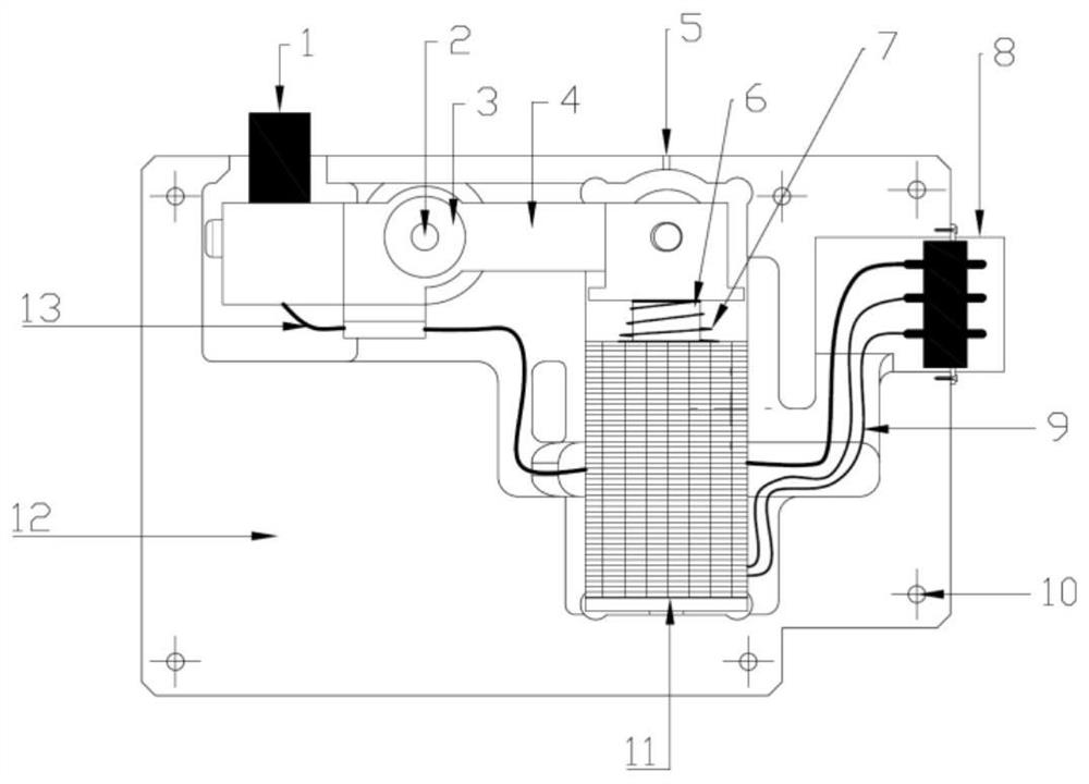
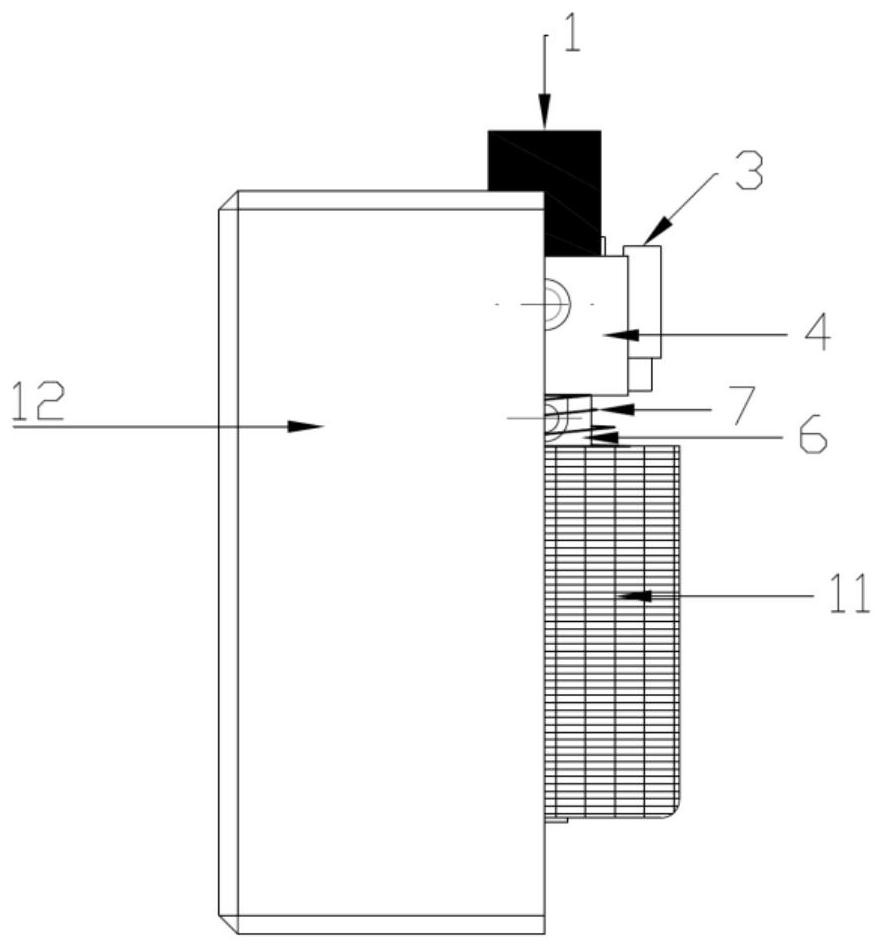
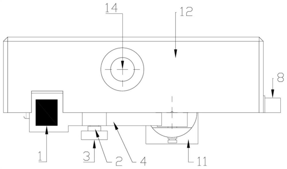
[0016] A generator rotor insulation monitoring brush device, including a lever device 4, the lever device 4 is fixed on the unit casing 12 through a lever shaft 2 and bearings 3 on both sides, one end of the lever device 4 is slotted into a carbon brush 1, and the carbon brush is drawn out The wire 13 is passed through the lever device 4 and led out from the lower part thereof, and finally connected to the aviation plug 8 . The other end of the lever device 4 is connected with an iron core 6, and the iron core 6 and the lever device 4 are movably connected. The iron core 6 is inserted into the electromagnetic coil 11 after passing through the spring 7, and the spring 7 is located between the electromagnetic coil 11 and the lever device 4. At the same time, when the iron core 6 after the electromagnetic coil 11 is energized is subjected to the downward electromagnetic attraction force, the spring 7 is compressed, the iron core 6 drives the lever device 4 to move down, and the ca...
PUM
 Abstract
Description
Claims
Application Information