Valve pair sealability detection device and method

A sealing detection and valve pairing technology, which is applied in fluid tightness testing, measuring devices, liquid tightness measurement using liquid/vacuum degree, etc. It can solve the problem of small swing range of pressure gauge pointer, lower pressure gauge reading, leakage To improve the accuracy of sealing detection and improve the quality of sealing

Pending Publication Date: 2018-06-29
SICHUAN AOWEI OIL EXTRACTION EQUIP CO LTD
View PDF7 Cites 8 Cited by
  • Summary
  • Abstract
  • Description
  • Claims
  • Application Information

AI Technical Summary

Problems solved by technology

[0006] At present, the conventional detection device and method are to use a vacuum pump to evacuate. After reaching a higher vacuum pressure, the pressure is maintained for a certain period of time, and then it is judged whether the sealing is qualified by observing whether there is a pressure drop in the reading of the vacuum pressure gauge. The defect of the method is that it is impossible to visually observe whether there is leakage between the valve ball and the valve seat seal. Due to the limitation of the accuracy of the vacuum pressure gauge and the sensitivity of the needle, when there is a slight leakage, the pressure gauge pointer cannot reflect it, or the pressure gauge pointer The swing range is very small, and it is not easy to be noticed by the inspector within the specified time
And when the pipeline or control valve and other systems of this detection device leak, it will also cause the reading of the pressure gauge to decrease, resulting in misjudgment.
Therefore, the detection accuracy and detection efficiency of this detection method are not high

Method used


Image

  • Valve pair sealability detection device and method

Examples


Embodiment Construction

[0035] The valve pair leak detection device of the present invention will be described in detail below in conjunction with the accompanying drawings.

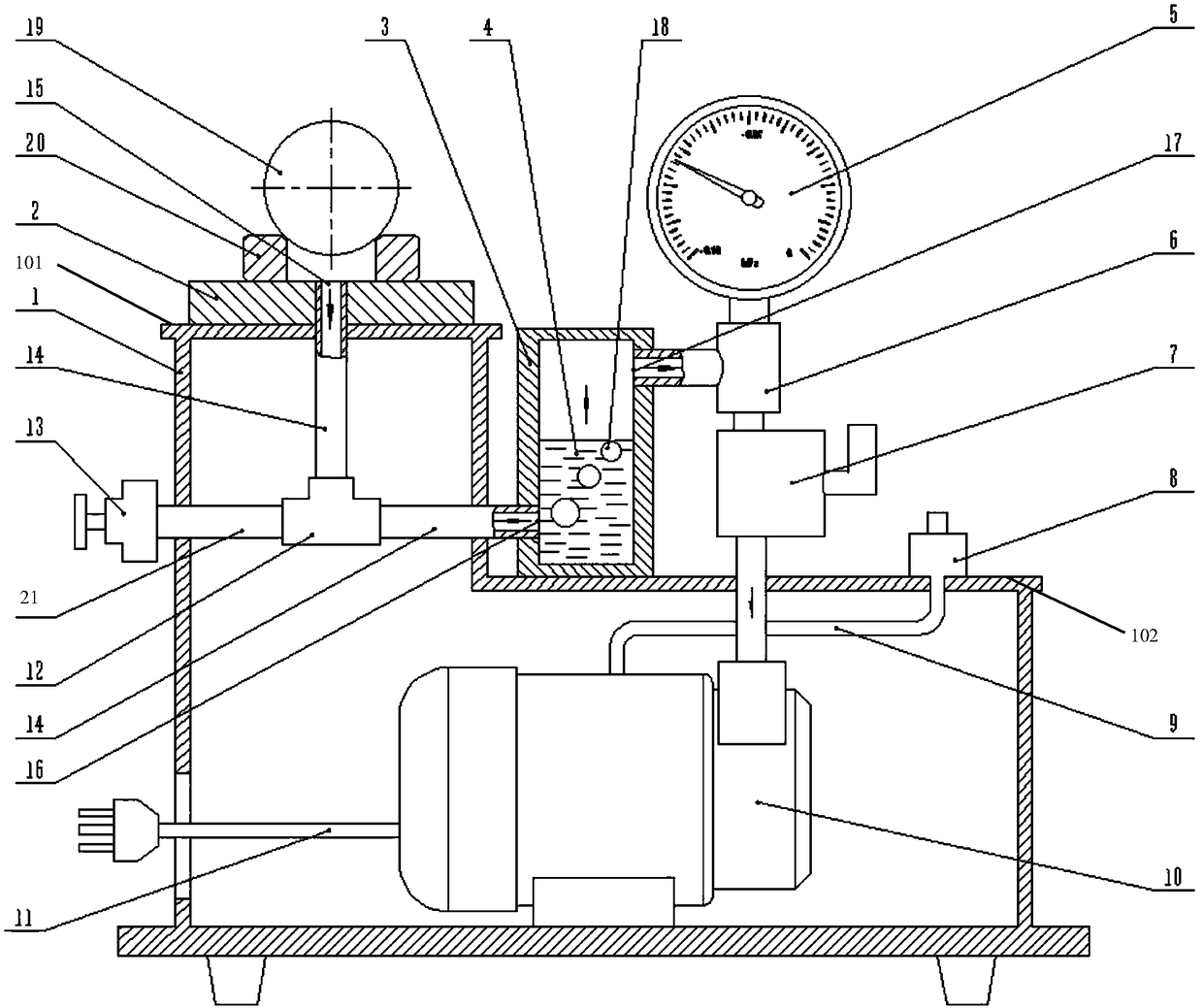
[0036] figure 1 It is a structural schematic diagram of the valve pair leak detection device of this embodiment. It shows a preferred embodiment of the valve pair leak detection device of the present invention.

[0037] Such as figure 1 As shown, a valve pair leak detection device includes a detection table 2 , a leakage observation chamber 3 , a vacuum pressure gauge 5 , a pressure maintaining valve 7 and a vacuum pump 10 .

[0038] The detection platform 2 communicates with the leakage observation chamber 3 through a pipeline 14 . Preferably, the leakage observation chamber 3 is a transparent sealed cylinder or a transparent square sealed box.

[0039] In the state of use, the tested valve pair formed by the valve ball 19 and the valve seat 20 is installed on the testing platform 2 and communicates with the pipeline 14 th...


PUM


Abstract

The invention relates to a valve pair sealability detection device and method. The device comprises a detection platform, a leakage observation chamber, a vacuum pressure meter, a pressure maintainingvalve and a vacuum pump, the detection platform is communicated with the leakage observation chamber through a pipeline, a detected valve pair is mounted on the detection platform and communicated with the pipeline through a detection platform air suction port, bubble observation liquid is filled in the leakage observation chamber, and liquid level of the bubble observation liquid is higher thanan observation box air suction port formed at a position where the pipeline is connected with the leakage observation chamber; the leakage observation chamber is connected with the vacuum pressure meter and the pressure maintaining valve through a pressure meter three-way joint, liquid level of the bubble observation liquid is lower than an observation box air exhaust port formed at a position where the leakage observation chamber is connected with the pressure meter three-way joint and the detection platform air suction port, and the pressure maintaining valve is connected with the vacuum pump. By the valve pair sealability detection device and method, sealability detection accuracy, detection efficiency and detection standards of the valve pair for an oil pump can be improved, and sealability quality of the valve pair is improved.

Description

technical field [0001] The invention relates to the technical field related to the detection of petroleum exploitation equipment, in particular to a valve pair sealing performance detection device and detection method. Background technique [0002] At present, oil well pumps used in the field of oil and gas exploitation must use two or more sets of valve balls and valve seats to form the oil inlet and outlet valve pairs of oil well pumps. Valve balls and valve seats are the core components of oil well pumps. At the same time, it is a consumable part. [0003] The valve ball and the valve seat are sealed by a sealing band ground on the valve seat. The sealing failure of valve ball and valve seat is the main failure mode of oil well pump. [0004] The oil pump is installed in the underground oil well to extract crude oil, and the working condition is very bad. If the sealing of the valve ball and the valve seat is not good, or there is a slight leakage that is not detected w...

Claims


Application Information

Patent Timeline
Patent Type & Authority Applications(China)
IPC IPC(8): G01M3/08G01M3/28
CPCG01M3/086G01M3/2876
Inventor 高宏吴伟李京萍
Owner SICHUAN AOWEI OIL EXTRACTION EQUIP CO LTD
Why Eureka
Try Eureka