Micromirror-based time division shared window laser radar system

A laser radar and micromirror technology, applied in the field of time-division shared window laser radar system, can solve the problems of increasing system size and cost, complex receiving optical path, and difficulty in applying portable devices

Active Publication Date: 2018-06-29
WUXI INFISENSE PERCEPTION TECH CO LTD
View PDF22 Cites 6 Cited by
  • Summary
  • Abstract
  • Description
  • Claims
  • Application Information

AI Technical Summary

Problems solved by technology

The disadvantage of the laser radar system with separate transceivers is that the direction distribution of the echo light field is relatively

Method used


Image

  • Micromirror-based time division shared window laser radar system
  • Micromirror-based time division shared window laser radar system
  • Micromirror-based time division shared window laser radar system

Examples


Embodiment 1

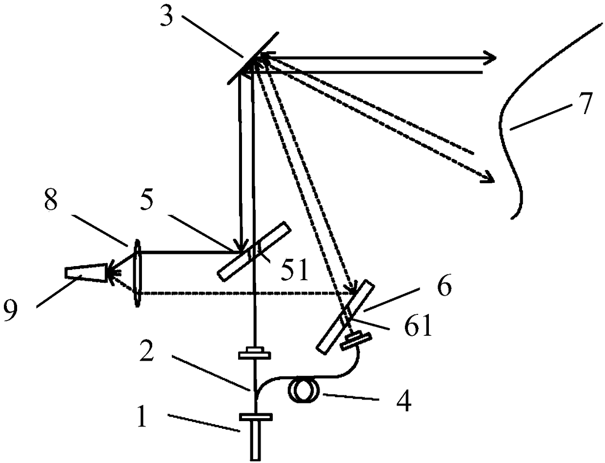
[0028] Such as figure 1 As shown, the present invention provides a time-division shared window lidar system based on a micromirror, comprising: a laser 1, an optical fiber beam splitter 2, a first single-sided mirror 5, a micromirror 3, and a second single-sided mirror 6 , Converging lens 8, photodetector 9 and delay fiber 4.

[0029] A first through hole is opened on the first one-way reflector 5; a second through hole is opened on the second one-way reflector 6;

[0030] The laser beam generated by the laser 1 is divided into two paths by the optical fiber beam splitter 2, and one path of the laser beam is emitted to the micromirror 3 through the first through hole, and then emitted to the detection target through the micromirror 3 7. The other laser beam is emitted to the second single-sided mirror 6 after passing through the time-delay optical fiber 4, and is emitted to the micromirror 3 through the second through hole, and is emitted to the detection target 7 through the...

Embodiment 2

[0051] In the lidar system described in Embodiment 1, the micromirror 3 is an important optical relay component and scanning device in the optical path. On the one hand, the size of the reflection surface of the micromirror 3 defines the maximum reflection area; on the other hand, the micromirror 3 realizes the scanning of the light beam based on its own scanning structure.

[0052] Further, the micromirror 3 is a dynamically deformable micromirror.

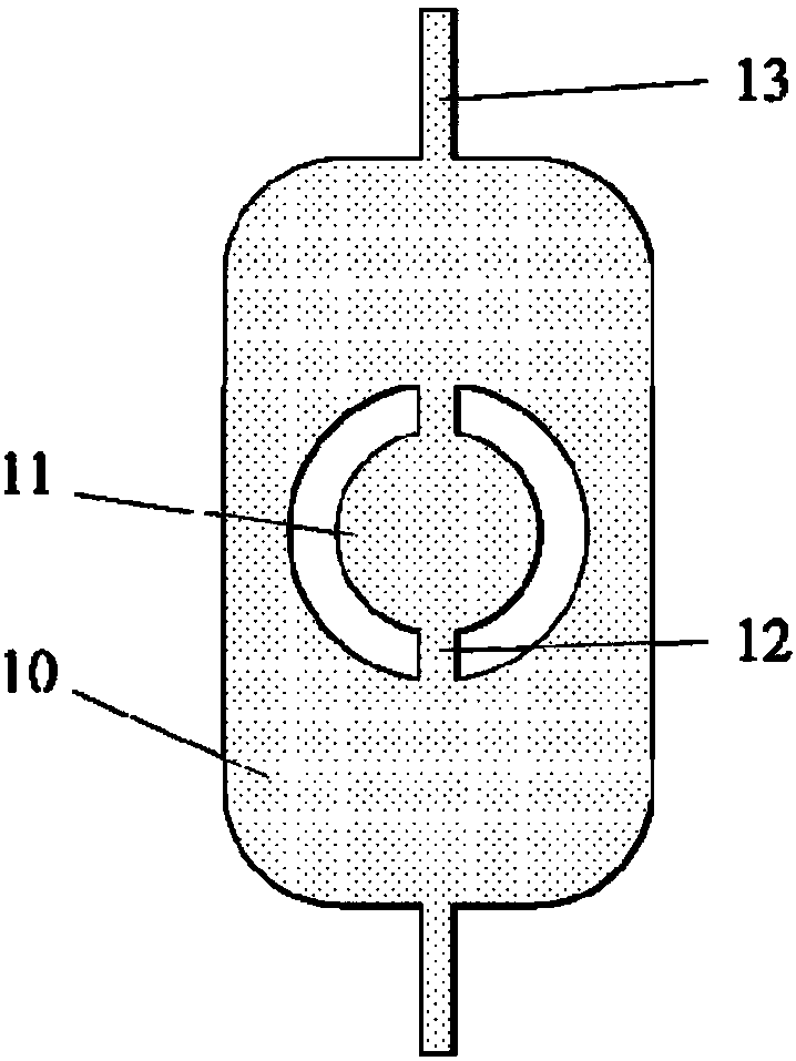
[0053] In the present embodiment two, the basic structure of the mirror surface of the micromirror 3 is as follows: figure 2 As shown, it includes an outer mirror 10 and an inner mirror 11. The inner mirror 11 is connected to the outer mirror 10 via a connecting mechanism 12, and the outer mirror 10 is connected to an external fixed anchor point through a torsion shaft 13. The outer mirror 10, the inner mirror 11 and the connection mechanism 12 form a whole to rotate around the rotation axis, and the connection mechanism 12 is ...

Embodiment 3

[0057] exist figure 2 A structure of the micromirror 3 is shown in , in which the inner mirror 11 is rotated about the axis of rotation. During the rotation and oscillation process, the natural rotational frequency of the micromirror as a whole is determined by the total moment of inertia of the micromirror and the stiffness coefficient of the torsion axis 13 . Therefore, by adjusting the shape and size of the connecting mechanism 12, the overall rotation frequency of the micromirror is much lower than the natural frequency of the vibrator formed by the connecting mechanism 12 and the inner mirror 11. The size of the connecting mechanism 12 can be adjusted by adjusting the first width ( H1 ) and the first distance ( L1 ), and the shape of the connecting mechanism 12 can be formed by changing the etched pattern.

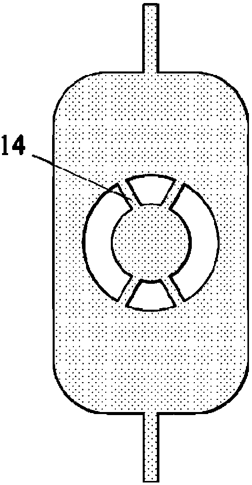
[0058] exist image 3 In the micromirror structure shown, four arc-shaped grooves are etched on the same circumference on the SOI with the center of the inner mirr...


PUM


Abstract

The invention discloses a micromirror-based time division shared window laser radar system. A first through hole is formed in a single-face reflector; a second through hole is formed in a second single-face reflector; a laser beam generated by a laser is divided into two paths; one path of laser beam is emitted to a micromirror through the first through hole and then is emitted to a detection target through the micromirror; the other path of laser beam is emitted to the second single-face reflector after passing through delay optical fiber, is emitted to the micromirror through the second through hole and is emitted to the detection target through the micromirror; and an echo light beam reflected by the detection target is reflected to the first single-face reflector and the second single-face mirror by the micromirror and then is converged to a light detector through a converging lens. The echo light beams of two beams of emergent laser are separated in a time domain by the delay optical fiber, so that two paths of echo light beams can be detected simultaneously by one group of detector, the system structure is further simplified, the volume of the system and the number of parts are reduced, the cost is saved and the assembling precision of the system is reduced.

Description

technical field [0001] The invention relates to a laser radar, in particular to a time-division sharing window laser radar system based on a micromirror. Background technique [0002] LiDAR is a high-precision distance measurement device. As an active detection device, lidar is not affected by day and night and has strong anti-interference ability. In addition to applications in fields such as terrain mapping, it has also attracted great attention in the fields of autonomous driving and drones in recent years. Traditional lidar uses multiple lasers combined with the design of mechanical rotating structure, which is not only slow and bulky, but also high energy consumption and high cost. Using a micromirror instead of a mechanical rotating structure can greatly reduce the size of the device, increase the scanning frequency, and consume less energy. In addition, since the micromirror can form a one-dimensional scanning mirror surface and scan in a two-dimensional surface, o...

Claims


Application Information

Patent Timeline
IPC IPC(8): G01S17/02G01S7/481
CPCG01S7/481G01S7/4811G01S7/4818G01S17/02
Inventor 虞传庆王鹏陈文礼王宏臣孙丰沛董珊
Owner WUXI INFISENSE PERCEPTION TECH CO LTD
Why Eureka
Try Eureka