Collimating structure, manufacturing method thereof and display device

A technology for display panels and light-shielding layers, which is applied in optics, instruments, character and pattern recognition, etc. It can solve problems such as excessive distance between objects and optical sensing structures, light crosstalk, etc., so as to reduce the difficulty of processing technology and improve accuracy , good collimation effect

Active Publication Date: 2018-06-29
BOE TECH GRP CO LTD
View PDF4 Cites 30 Cited by
  • Summary
  • Abstract
  • Description
  • Claims
  • Application Information

AI Technical Summary

Problems solved by technology

[0003] In view of this, embodiments of the present invention provide a collimation structure, its manufacturing method, and a display device to solve the problem of light crosstalk that exists when the distance between the object and the optical sensing structure is too large during the image acquisition process

Method used


Image

  • Collimating structure, manufacturing method thereof and display device
  • Collimating structure, manufacturing method thereof and display device
  • Collimating structure, manufacturing method thereof and display device

Examples


Embodiment Construction

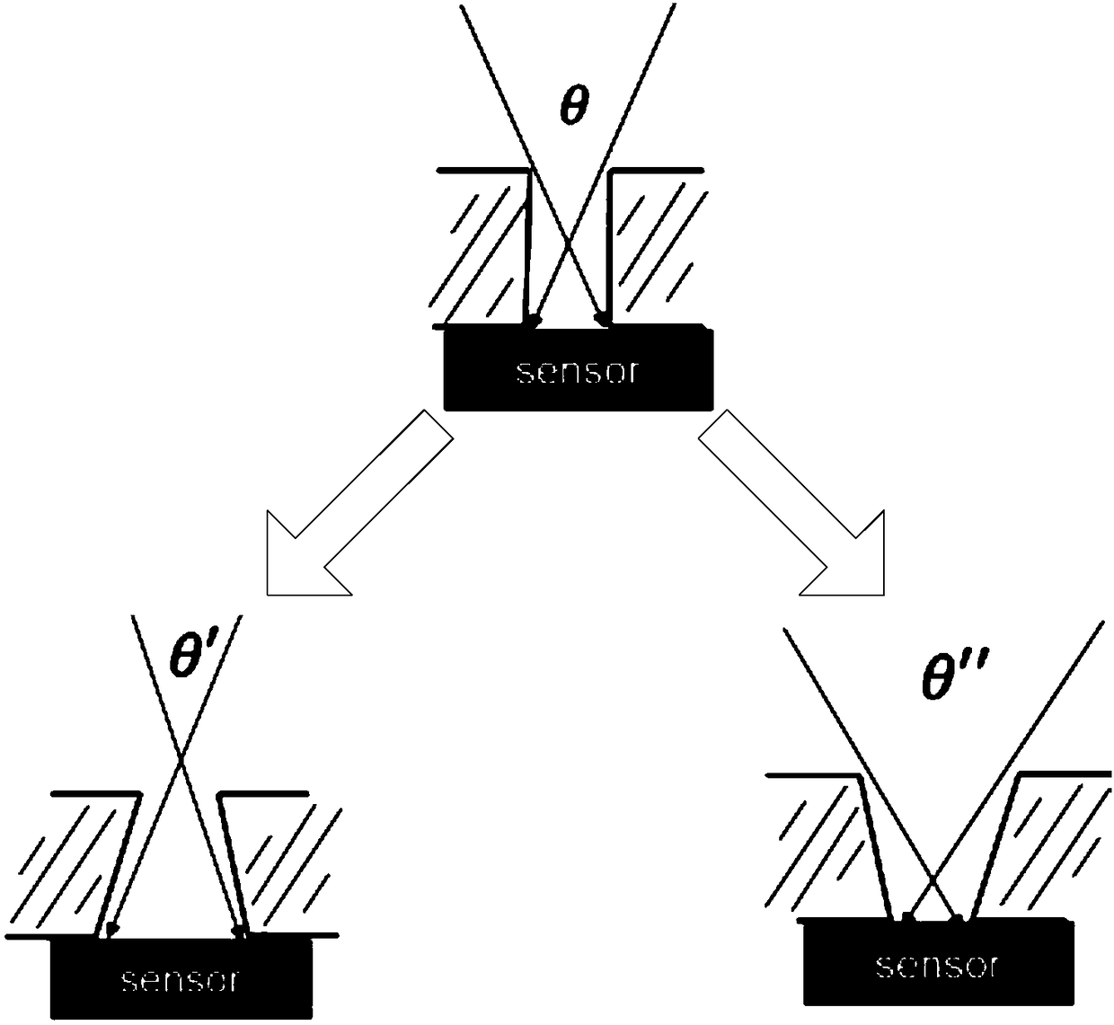
[0042] At present, in the process of optical pattern recognition, when the distance between the finger and the sensor is large, the obtained image will be blurred due to the scattering of the light reflected by the finger, which in turn leads to the pattern that is recognized based on the light received by the sensor The problem of inaccurate information. In order to accurately obtain the information of the valleys and ridges of the texture, at present, the through-hole filter method and the lens and diaphragm method are generally used, and a collimating structure is added to the sensor. The through-hole structure requires specific materials to achieve a high aspect ratio, such as figure 1 As shown, the existing process will have a similar “chamfer” structure in the lithography process, and it cannot guarantee that the sidewall of the through-hole structure is strictly perpendicular to the light incident surface, so that the light receiving angle becomes larger, and the light in...


PUM


Abstract

The invention discloses a collimating structure, a manufacturing method thereof and a display device. The collimating structure which is provided with light holes and formed by multiple light blockinglayers is adopted, the distance between the light blocking layers is adjusted by light transmitting layers, so that the required depth-width ratio of sleeve holes is reached, and a light receiving angle of the collimating structure is limited. A better collimation effect can be achieved by only manufacturing the multiple light blocking layers and the light transmitting layers with a relatively simple structure, and the device is lighter and thinner in structure, so that the processing / machining difficulty of the device can be reduced. Besides, at least one middle light blocking layer locatedbetween the top light blocking layer and the bottom light blocking layer is arranged, distance between the light blocking layers is adjusted by the light transmitting layers, and light ray interference among the light holes can be blocked, so that accuracy of identified grain information can be improved.

Description

Technical field [0001] The present invention relates to the field of display technology, in particular to a collimating structure, a manufacturing method thereof, and a display device. Background technique [0002] In the optical image acquisition process, when the distance between the object and the optical sensing structure is too large, the acquired image will be blurred, and the light of the acquired object has crosstalk problems, resulting in the final inability to obtain a clear image of the object. Summary of the invention [0003] In view of this, embodiments of the present invention provide a collimating structure, a manufacturing method thereof, and a display device to solve the problem of light crosstalk that exists when the distance between the object and the optical sensing structure is too large during the image acquisition process. [0004] Therefore, the embodiment of the present invention provides a collimating structure, including: a plurality of light blocking lay...

Claims


Application Information

Patent Timeline
Patent Type & Authority Applications(China)
IPC IPC(8): G02B27/30
CPCG02B27/30G02B2207/123G02B5/005G06V40/1324G06V40/1318
Inventor 海晓泉董学王海生刘英明王雷许睿
Owner BOE TECH GRP CO LTD
Why Eureka
Try Eureka