
Separator plate, membrane electrode assembly and fuel cell

一种燃料电池、分离器的技术,应用在燃料电池、燃料电池的零部件、收集器/分离器等方向,达到低电流强度、减小功率密度、电流减小的效果

Active Publication Date: 2018-06-29
VOLKSWAGEN AG +1
View PDF3 Cites 2 Cited by
  • Summary
  • Abstract
  • Description
  • Claims
  • Application Information

AI Technical Summary

Problems solved by technology

Additional costs for additional components are associated with this

Method used

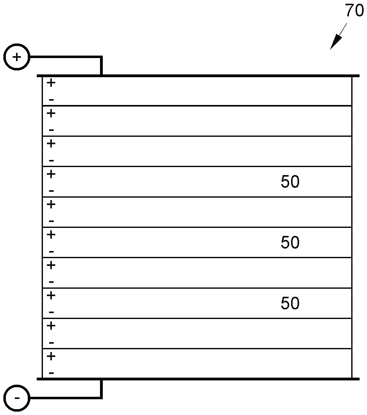
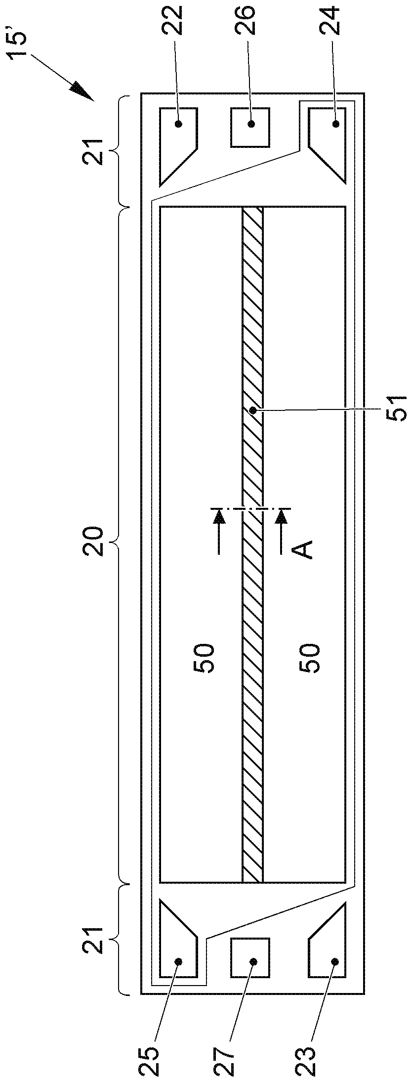

Image

  • Separator plate, membrane electrode assembly and fuel cell
  • Separator plate, membrane electrode assembly and fuel cell
  • Separator plate, membrane electrode assembly and fuel cell

Examples


Embodiment Construction

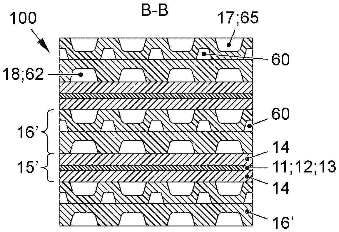
[0051] Figure 1A A section of a fuel cell stack, indicated overall at 100 , of which only two individual fuel cells 10 are shown here, is shown. Each fuel cell 10 has a polymer electrolyte membrane 11 made of an electrolyte-conducting, in particular proton-conducting, polymer material. Typically, polymeric materials require a certain humidity in order to maintain their electrolyte conductivity. A respective catalyst layer, namely the anode catalyst layer 12 and the cathode catalyst layer 13 adjoins both sides of the membrane 11 . Catalyst layers 12 and 13 comprise a catalytic material, typically a noble metal, especially platinum. Typically, the catalyst layers 12 , 13 also comprise a porous, electrically conductive carrier material on which a catalytic material, for example a carbon-based material, is finely dispersed. The catalyst layers 12, 13 may comprise further components such as polymeric binder materials and the like.

[0052] A respective gas diffusion layer (GDL)...


PUM


Abstract

The invention relates to a separator plate, a membrane electrode assembly and a fuel cell stack. The invention relates to a separator plate (16'), a membane-electrode-unit (15'), and a fuel cell stack, which are designed for high voltage. It is provided that in the active region at least one of the cell components contains at least one insulating element which permanently enables different electrical potentials in a cell plane (orthogonal to the stacking direction).

Description

technical field [0001] The invention relates to a separator plate, a membrane-electrode unit and a fuel cell comprising said separator plate, membrane-electrode unit. Background technique [0002] Fuel cells use the electrochemical conversion of fuel and oxygen into water to generate electricity. For this purpose, the fuel cell comprises as a core component a so-called membrane-electrode-unit (MEA, membrane electrode assembly: membrane-electrode assembly), which is composed of an ion-conducting, in particular proton-conducting, membrane and respectively arranged in the A complex of electrodes (anode and cathode) on both sides of the membrane. Furthermore, a gas diffusion layer (GDL) can be arranged on both sides of the membrane-electrode unit on the side of the electrode facing away from the membrane. Generally, a fuel cell is constituted by a plurality of battery cells arranged in a stack, including a separator plate and an MEA, whose electric power is added. In the oper...

Claims


Application Information

Patent Timeline
Patent Type & Authority Applications(China)
IPC IPC(8): H01M8/0258H01M8/1004H01M8/2483
CPCH01M8/2483H01M8/0258H01M8/1004H01M8/0202H01M8/1018H01M2008/1095H01M8/083H01M8/086H01M8/1011H01M8/0223H01M8/0267H01M2008/1293H01M2008/147H01M8/2418H01M8/0221Y02E60/50
Inventor H.肖尔茨M.雷克斯L.拉肯马歇尔
Owner VOLKSWAGEN AG
Learn More