Pilot signal design method used for maximizing effect and large-scale multi-antenna system

A technology of pilot signal and design method, applied in the directions of pilot signal distribution, radio transmission system, transmission system, etc.

Active Publication Date: 2018-06-29
ZHENGZHOU UNIVERSITY OF AERONAUTICS
View PDF5 Cites 16 Cited by
  • Summary
  • Abstract
  • Description
  • Claims
  • Application Information

AI Technical Summary

Problems solved by technology

Therefore, when designing pilot signals, it is necessary to use more comprehensive energy efficiency performance as a criterion to achieve a compromise between system over

Method used


Image

  • Pilot signal design method used for maximizing effect and large-scale multi-antenna system
  • Pilot signal design method used for maximizing effect and large-scale multi-antenna system
  • Pilot signal design method used for maximizing effect and large-scale multi-antenna system

Examples


Embodiment Construction

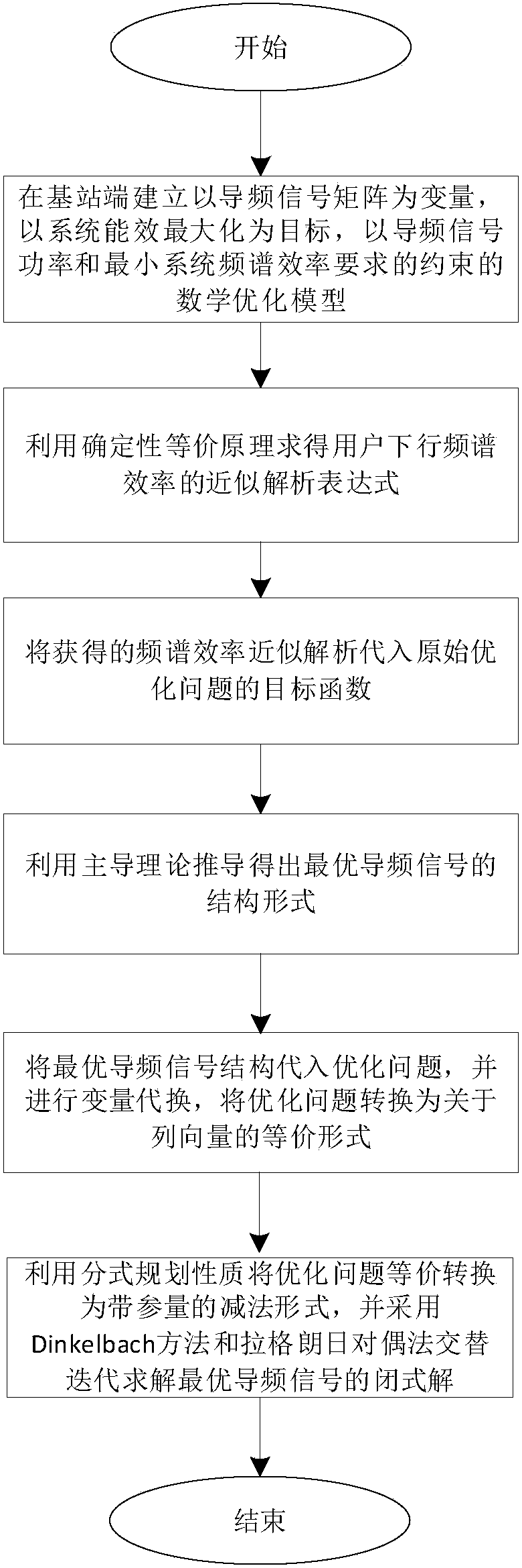
[0077] to combine figure 2 The shown algorithm flow chart specifically explains a kind of energy efficiency maximization pilot signal design method based on frequency division duplex large-scale multi-antenna system of the present invention, comprising the following steps:

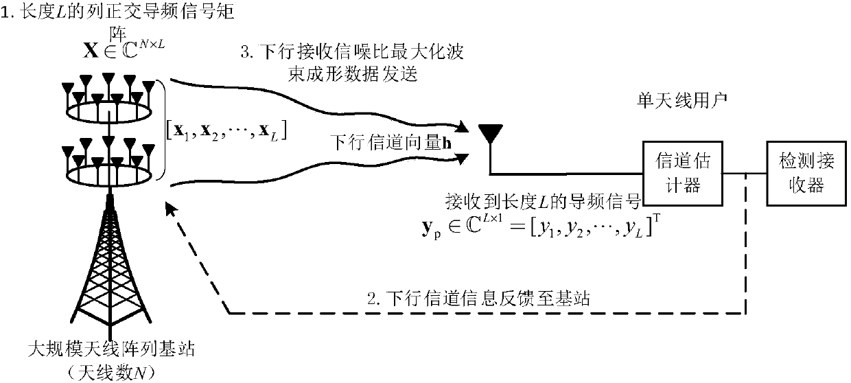
[0078] 1). The base station and the user adopt the frequency division duplex system, the uplink and downlink channels do not satisfy reciprocity, the channel obeys flat block fading, and has a coherent duration T c (in symbol duration); the base station passes the downlink channel vector Send the pilot signal and the beamforming vector successively, Represents the base station antenna array spatial correlation matrix, and TrR=N, R can be decomposed into R=UΛU H , Λ=diag{[λ 1 ,λ 2 ,...λ K ]} represents a K×K dimensional diagonal matrix composed of non-zero eigenvalues ​​of R, and U is an N×K unitary matrix composed of eigenvectors corresponding to non-zero eigenvalues ​​of R; the channel vector can ...


PUM


Abstract

The invention discloses a pilot signal design method used for maximizing effect and a large-scale multi-antenna system. The system is constituted by a base station configured with a large-scale antenna array and a user configured with a single antenna. The base station is used to transmit a downlink pilot signal to the user, and channel estimation is completed on a user terminal, and then estimation information is fed back to the base station, and then the base station adopts a maximized received signal-to-noise ratio wave beam forming scheme for data transmission. According to the invention,by taking the maximization of the system effect as an object, and the pilot signal as an optimization variable, a mathematical model is established; by adopting a certainty equivalency principle, an approximate analytical expression of a target function is acquired, and then the structure of the optimal pilot signal is deduced by adopting a majorization theory; properties are planned according tofractions, and an original optimization problem is converted into an equivalent subtraction form, and therefore an iterative optimization algorithm is acquired, and then by adopting a Lagrange dualitymethod, the closed-form solution of the optimal pilot signal is acquired.

Description

technical field [0001] The invention belongs to the technical field of wireless communication, and in particular relates to a pilot signal design method for maximizing energy efficiency and a large-scale multi-antenna system. Background technique [0002] Since it was proposed in 2010, massive multiple-input multiple-output (massive MIMO) technology has attracted the attention of the wireless communication industry with its novel physical characteristics, and is generally considered to be one of the core technologies of the physical layer of the fifth-generation mobile communication system. one. Massive MIMO technology refers to configuring a large number of antenna arrays at the base station to simultaneously serve a relatively small number of multiple users, thereby obtaining many performance advantages different from traditional MIMO systems. For example, the base station adopts a simple linear Precoding / detection method to effectively eliminate multi-user interference, ...

Claims


Application Information

Patent Timeline
IPC IPC(8): H04L5/00H04B7/0413H04L25/02
CPCH04B7/0413H04L5/0048H04L25/0204H04L25/0226Y02D30/70
Inventor 王毅马鹏阁张松炜杨少川闫利超刘兆瑜郭荣幸张宏亮王丹赵飞刘亚黄开枝许晓明王兵陶然
Owner ZHENGZHOU UNIVERSITY OF AERONAUTICS
Why Eureka
Try Eureka