Negative carbon emission system and method thereof

An emission system and negative carbon technology, applied in horticultural methods, botanical equipment and methods, energy saving and emission reduction, etc., can solve problems such as rising net carbon dioxide concentration

Inactive Publication Date: 2018-07-03
刘容生
View PDF7 Cites 3 Cited by
  • Summary
  • Abstract
  • Description
  • Claims
  • Application Information

AI Technical Summary

Problems solved by technology

[0003] Congress also recognized that clean power generation technologies and energy efficiency measures alone are not sufficient to address the underlying problem because net carbon dioxide concentrations are still rising even as the amount of carbon dioxide is reduced and emitted at a slower rate

Method used


Image

  • Negative carbon emission system and method thereof
  • Negative carbon emission system and method thereof
  • Negative carbon emission system and method thereof

Examples


example 1

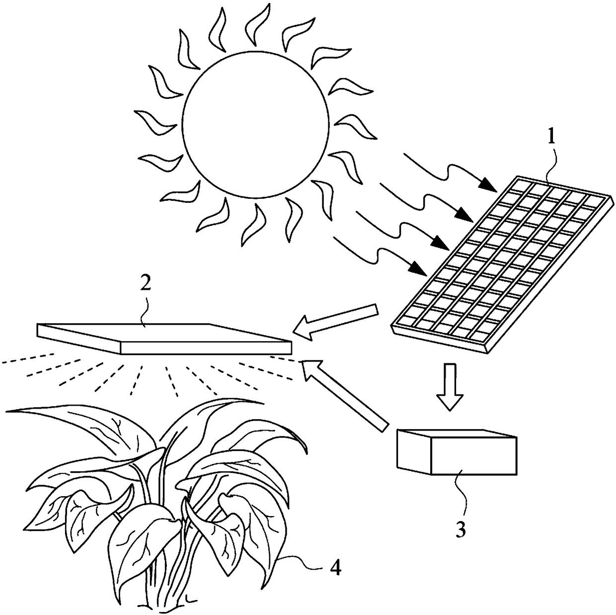
[0077] figure 1 Depict the components that implement the carbon negative emission system of the present invention. Assembly 1 depicts a solar panel that can be positioned to face the sun. Assembly 2 depicts an LED light source, which in an embodiment is arranged to shine directly on growing vegetation 4 like eg algae. Assembly 3 depicts the battery connected to the solar panel 1 and the LED light source 2 . Assembly 3 may include a voltage converter that converts the DC voltage from the solar panel into AC voltage.

[0078] As mentioned earlier, both solar panels and LED light sources come with their own carbon footprint. According to the inventor's calculations, First Solar's exemplary solar panel has a carbon footprint of 6.15g CO 2 e / KWh while Osram's exemplary LED has 3.65g CO 2 Carbon footprint in e / KWh. As analyzed earlier in this article, when the LED light source guides the growing plants, the combination of the solar panel and the LED light source can eliminate ...

example 2

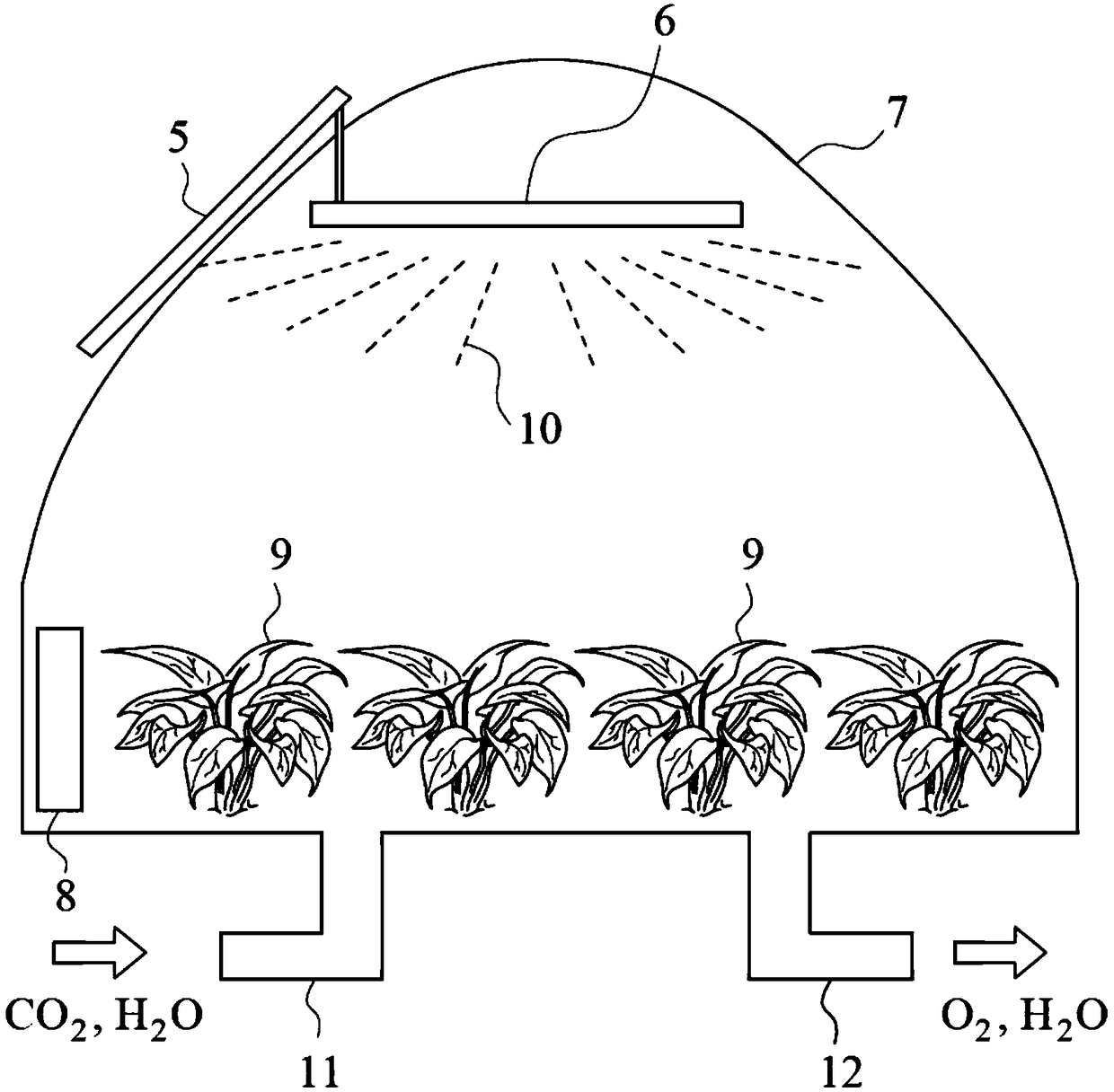
[0080] figure 2 Depicting another embodiment of the invention, the system comprises solar panels 5 fixed to a greenhouse 7 in which photosynthetic plants such as algae grow. Solar panels with a carbon footprint of 6.15 gCO2e / kWh or less, connected directly to an LED light source6, or indirectly via a battery, as shown in component 8, with an LED carbon footprint of 3.65 gCO2e / kWh or less few. When photons 10 are directed to growing plants 9 including algae, this system is not only capable of eliminating CO from the combination of solar panels and LED light sources 2 Emissions can remove more carbon dioxide from the atmosphere. Assembly 8 includes an optional voltage converter that converts the DC voltage from the solar panel to AC voltage. also, figure 2The shown system may also include: a first air guide system 11 for introducing carbon dioxide and moisture to provide to the growing plants; a second air guide system 12 for exporting the oxygen produced by the growing pl...

example 3

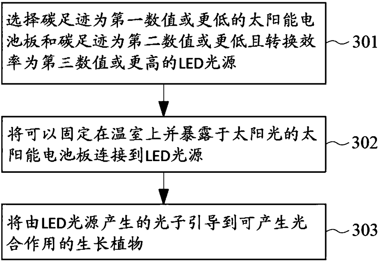
[0082] image 3 Describe the construction process by which a carbon negative emission system can be achieved. The process includes the following steps. Step 301, select the carbon footprint as the first value such as 6.15g CO 2 e / KWh or lower solar panels and carbon footprint as a second value eg 3.65g CO 2 An LED light source with e / KWh or lower and a conversion efficiency of a third numerical value such as 30.4% or higher. At step 302, a solar panel, which may be fixed on the greenhouse and exposed to sunlight, is connected to the LED light source, wherein the solar panel may also be connected to the LED light source through a battery and a converter. In step 303, the photons generated by the LED light source are guided to photosynthetic growing plants such as algae, and the surface of the algae can absorb most of the photons. In addition, the following steps may be further added: providing a first air guide system for introducing carbon dioxide and moisture to the growi...


PUM


Abstract

The invention discloses a negative carbon emission system and a method thereof. Carbon dioxide molecules can be fixed by growing plants through plant photosynthesis. When the wavelength of photons that cause the plant synthesis are properly designed to enhance plant photosynthesis of plants. A LED light source, whose carbon footprint is lower than a threshold value and the conversion efficiency ishigher than a threshold value, is adopted. A low carbon power supply with carbon footprint lower than a threshold value such as a solar panel is used. When the combination is realized, carbon dioxidemolecules absorbed by plants through photosynthesis are more than emitted carbon dioxide molecules, long term negative carbon emission is realized, and the system can be used to capture carbon dioxide.

Description

technical field [0001] The invention relates to a negative carbon emission system and a method thereof. Background technique [0002] The high concentration of carbon dioxide (CO2) in the Earth's atmosphere 2 ) threatens the future way of life on Earth. Countries are taking measures to reduce carbon dioxide emissions in the atmosphere, including exploring more energy-saving power generation technologies to promote energy conservation and reduce carbon dioxide emissions. At the United Nations Climate Change Conference held in Paris in 2015, more than 187 member countries set an aggressive goal to limit the rise in global temperature to below 1.5°C and return to pre-industrial levels. [0003] Congress also recognized that clean power generation technologies and energy efficiency measures alone are not sufficient to address the underlying problem, as net CO2 concentrations continue to rise even as the amount of CO2 is reduced and emitted at a slower rate. In other words, it...

Claims


Application Information

Patent Timeline
Patent Type & Authority Applications(China)
IPC IPC(8): A01G9/18A01G7/04A01G33/00
CPCA01G7/045A01G9/18A01G33/00Y02A40/25Y02P60/14Y02P60/20Y02P90/50
Inventor 刘容生
Owner 刘容生
Why Eureka
Try Eureka