Tire with self-inflation device

A self-inflating, tire technology, used in tire measurement, tire parts, tire sidewalls, etc., can solve the problems of reduced durability of the tube 4, complex structure, difficult miniaturization, etc., to minimize the decrease in durability and enhance Noise performance, overall size reduction effect

Inactive Publication Date: 2018-07-03
KUMHO TIRE CO INC
View PDF15 Cites 0 Cited by
  • Summary
  • Abstract
  • Description
  • Claims
  • Application Information

AI Technical Summary

Problems solved by technology

[0010] Therefore, there is a problem in the prior art 1 that the durability of the tube 4 decreases as the tube 4 comes into contact with the rim flange 1a.
[0027] However, in the case of prior art 4, not only are two check valves used to prevent air backflow, but also the regulator is designed with a separate spring in consideration of the high pressure of the tire, so the structure becomes quite complicated, and difficult to miniaturize
[0028] Also, there is no fine-tuning to set preset tire pressures
[0029] Furthermore, the disadvantage has been pointed out that since the connection between the compression tube and the inlet and outlet is realized inside the bead portion of the tire, it is too difficult to be suitable for practical tires
[0032] Therefore, although there is an advantage of miniaturization of the valve (or regulator), there has been a problem that the durability of the pressure film 104 is lowered.

Method used


Image

  • Tire with self-inflation device
  • Tire with self-inflation device
  • Tire with self-inflation device

Examples


Embodiment Construction

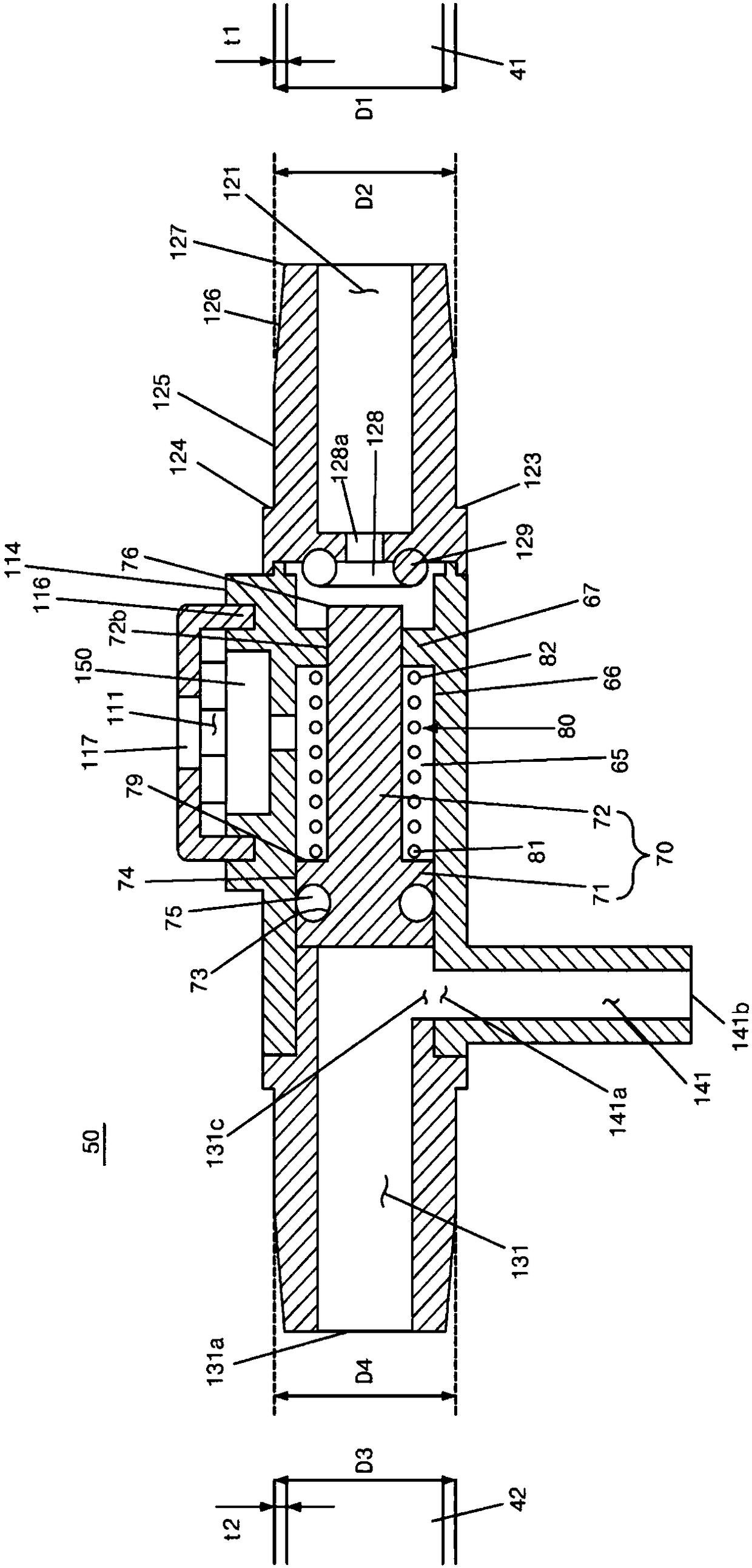
[0076] In the following, the regulator 50 will be described first as a focus.

[0077] The tire 10 of the present invention includes side portions.

[0078] The tube 40 is provided on the outside of the side portion 15 .

[0079] As the tire 10 is driven, as a telescoping movement takes place in the side 15 , a corresponding other telescoping movement takes place in the tube 40 provided in the side 15 .

[0080] The injection of air into the tire cavity 19 due to this telescopic movement in the side portion 15 and tube 40 will be described later.

[0081] The above-mentioned pipe 40 is connected to a regulator 50 .

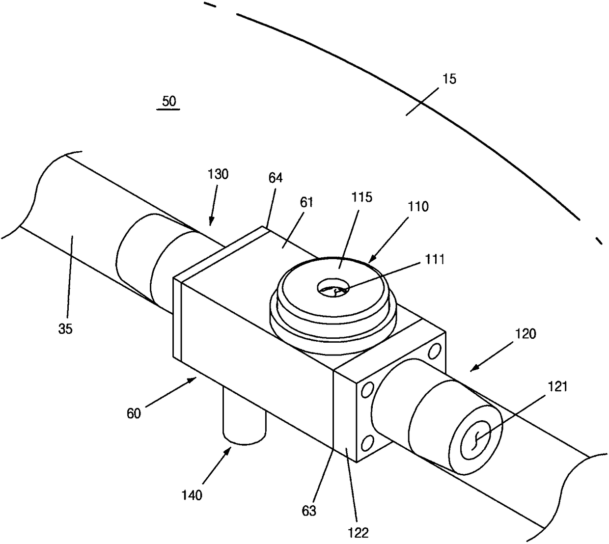
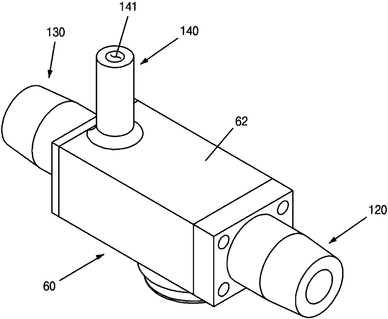
[0082] In the following, reference will be made to Figure 1 to Figure 3 The regulator 50 is described.

[0083] The overall shape of the adjuster 50 of the present invention is as follows.

[0084] The regulator 50 includes a body 60 .

[0085] In the main body 60, a plurality of ports 110, 120, 130, and 140 are formed to protrude from the upper side, the s...


PUM


Abstract

The present invention relates to a tire with self-inflation device wherein: (1) the tube is inserted inside the side portion wherein the extension and contraction movements of the tire are mostly occurring in order to further enhance the efficiency of the air supply to the tire cavity during driving; (2) the air compressed towards the driving direction is injected to the tire cavity, and the air from the outside is charged to the tube due to the negative pressure formed in the tube located in the opposite side of driving; and (3) the durability is enhanced by reducing the exposed portion of the regulator.

Description

technical field [0001] The present invention relates to a tire capable of maintaining proper air pressure by itself by supplementing air pressure leaked during tire operation by an air compression reaction due to expansion and contraction of a tube connected to a regulator. Background technique [0002] Typically, a small fraction of the air trapped in the tire and rim assembly will naturally leak out over time. [0003] When the air pressure of the tire is lower than the proper air pressure, the steering, braking and driving performance of the vehicle will be reduced. [0004] In order to maintain a preset air pressure of a tire, a related art tire pressure detection system measures pressure or temperature inside a tire using a tire pressure detection sensor installed in a wheel, and transmits the information to a control unit via wireless communication. [0005] However, the tire pressure detection system of the prior art simply warns the driver when the tire pressure dro...

Claims


Application Information

Patent Timeline
Patent Type & Authority Applications(China)
IPC IPC(8): B60C23/12
CPCB60C23/135B60C13/00F04B37/10F04B39/0005F04B39/10
Inventor 朴盛钟罗相度金亨錫成仁澈
Owner KUMHO TIRE CO INC
Why Eureka
Try Eureka