
Ionization radiation monitoring unmanned aerial vehicle, system and ionization radiation monitoring method

A technology of ionizing radiation and unmanned aerial vehicles, applied in the field of unmanned aerial vehicles, can solve the problems of poor positioning stability, unsteady monitoring and fluctuation of fixed-wing unmanned aerial vehicles

Pending Publication Date: 2018-07-03
BEIJING SENFU SCI & TECH CO LTD
View PDF7 Cites 4 Cited by
  • Summary
  • Abstract
  • Description
  • Claims
  • Application Information

AI Technical Summary

Problems solved by technology

However, this ionizing radiation monitoring method needs to collect ionizing radiation data at a hovering position when the fixed-wing UAV is close to the ground for ionizing radiation monitoring. Since the accuracy of GPS positioning is at the meter level, and there are many obstacles on the ground, the airflow Complicated, it is easy to interfere or block GPS signals, further reducing the accuracy of GPS positioning, making the positioning of fixed-wing UAVs fluctuate in a wider range, resulting in the inability of fixed-wing UAVs to hover stably for monitoring. Drift occurs in radiation hover monitoring, and the positioning stability is poor. Therefore, in the subsequent analysis process, the ionizing radiation source is located according to the ionizing radiation data obtained by monitoring, and the positioning accuracy is low.

Method used


Image

  • Ionization radiation monitoring unmanned aerial vehicle, system and ionization radiation monitoring method
  • Ionization radiation monitoring unmanned aerial vehicle, system and ionization radiation monitoring method
  • Ionization radiation monitoring unmanned aerial vehicle, system and ionization radiation monitoring method

Examples


Embodiment Construction

[0050] In order to make the purpose, technical solutions and advantages of the embodiments of the present application clearer, the technical solutions in the embodiments of the present application will be clearly and completely described below in conjunction with the drawings in the embodiments of the present application. Obviously, the described embodiments are only It is a part of the embodiments of this application, not all of them. The components of the embodiments of the application generally described and illustrated in the figures herein may be arranged and designed in a variety of different configurations. Accordingly, the following detailed description of the embodiments of the application provided in the accompanying drawings is not intended to limit the scope of the claimed application, but merely represents selected embodiments of the application. Based on the embodiments of the present application, all other embodiments obtained by those skilled in the art without...


PUM


Abstract

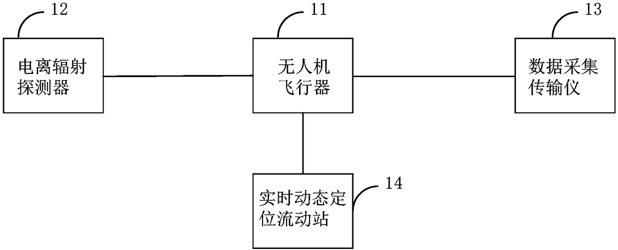
The invention provides an ionization radiation monitoring unmanned aerial vehicle, a system and an ionization radiation monitoring method. The flight control stability and positioning precision of anunmanned aerial vehicle can be improved, and accurate space ionization radiation monitoring and ionization radiation source searching are conducted. The ionization radiation monitoring unmanned aerialvehicle comprises an unmanned aerial vehicle aircraft, an ionization radiation detector, a data collecting and transmission instrument and real-time dynamic positioning moving stations. The ionization radiation detector, the data collecting and transmission instrument and the real-time dynamic positioning moving stations are carried on the unmanned aerial vehicle aircraft, and the ionization radiation detector and the real-time dynamic positioning moving stations are in signal connection with the data collecting and transmission instrument. The ionization radiation detector is mounted on thelower portion of a fuselage of the unmanned aerial vehicle aircraft. The data collecting and transmission instrument is mounted between the ionization radiation detector and the fuselage of the unmanned aerial vehicle aircraft. The real-time dynamic positioning moving stations are mounted on the two sides of the top of the unmanned aerial vehicle aircraft.

Description

technical field [0001] The present application relates to the technical field of unmanned aerial vehicles, in particular, to an ionizing radiation monitoring unmanned aerial vehicle, system and ionizing radiation monitoring method. Background technique [0002] Ionizing radiation is radiation that can ionize the subject matter, and is formed by directly or indirectly ionizing particles or a mixture of the two. Ionizing radiation has the characteristics of short wavelength, high frequency, and high energy. Therefore, if the protective measures are not appropriate, when the dose of human body exposure exceeds a certain limit, harmful effects can occur. Energy is released, causing cell damage, death, or transformation into cancer cells. Even if the dose of radiation to the human body does not exceed a certain limit, if a certain dose of radiation is scattered over a long period of time, it can cause chronic radiation damage, such as skin damage, hematopoietic disorders, leukop...

Claims


Application Information

Patent Timeline
IPC IPC(8): B64C39/02G05D1/08
CPCG05D1/0808B64C39/024B64U2101/00B64U2201/20
Inventor 陆德坚马天瑞欧阳溢
Owner BEIJING SENFU SCI & TECH CO LTD
Learn More