Terrestrial heat collecting device used in underground diaphragm walls

An underground continuous wall and collection device technology, applied in geothermal collectors, geothermal energy, household heating, etc., can solve the problems of limited contact area of ​​concrete, insufficient heat exchange efficiency, limited geothermal development and utilization, etc. Effects of mechanical properties, improved thermal conductivity, and improved heat exchange efficiency

Pending Publication Date: 2018-07-03
CHINA THREE GORGES UNIV
View PDF1 Cites 0 Cited by
  • Summary
  • Abstract
  • Description
  • Claims
  • Application Information

AI Technical Summary

Problems solved by technology

Today, as resource utilization continues to increase, it is very necessary to develop and utilize geothermal energy, and ground source heat pump technology was born. Ground source heat pump technology is a heating and cooling technology that uses shallow underground heat sources, which can reach The role of cooling in summer and heating in winter, the United States, Canada and some European countries have done in-depth research on geothermal pump technology and achieved remarkable results. However, the current development and utilization of geothermal in my country is quite limited. Due to the limitation of area, our country has not promoted and utilized it on a large scale. How to realize the efficient use of geothermal resources and rationally utilize the land area occupied by geothermal pumps is a problem worth studying.
[0003] Chinese patent (patent application No. 200910054306.4) discloses a "ground source heat pump buried pipe system buried in the enclosure structure of the underground diaphragm wall". Although the development and utilization of geothermal resources has been realized, it has the following shortcomings: (1) Through calculation and comparison analysis, it is found that the vertical pipe layout from the top of the wall to the bottom of the wall causes the temperature cycle of the heat transfer liquid to rise and fall during the circulation process. However, the heat exchange efficiency is not high enough; (2) The vertical arrangement of the heat pipes affects the mechanical performance of the underground diaphragm wall. When the wall deformation is large, the normal operation of the heat pipes may be affected; (3) The heat pipe cross section is Round shape, straight pipe in the length direction, limited contact area with concrete, and insufficient utilization efficiency of geothermal resources

Method used


Image

  • Terrestrial heat collecting device used in underground diaphragm walls
  • Terrestrial heat collecting device used in underground diaphragm walls
  • Terrestrial heat collecting device used in underground diaphragm walls

Examples


Embodiment Construction

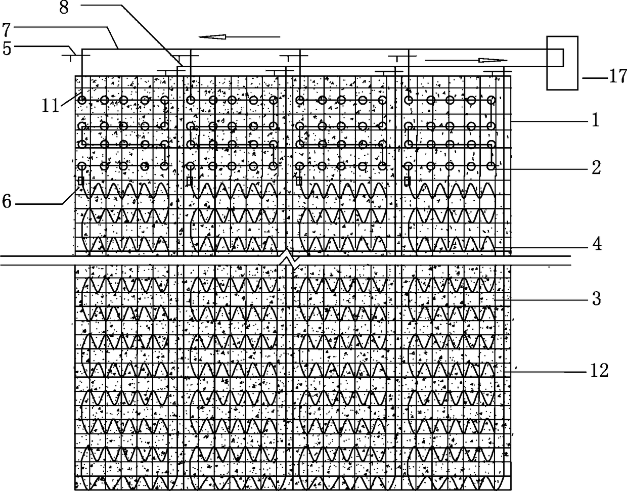
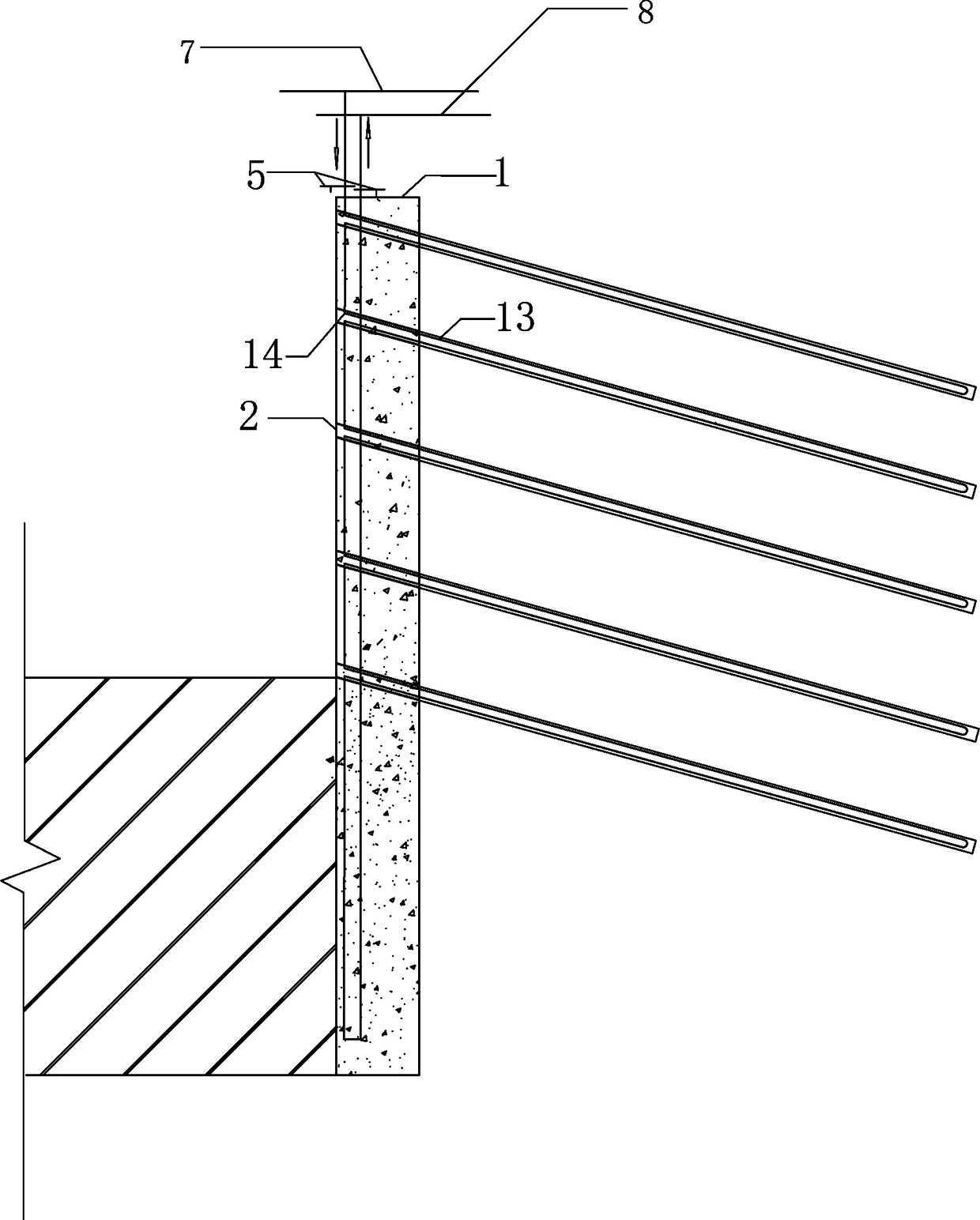
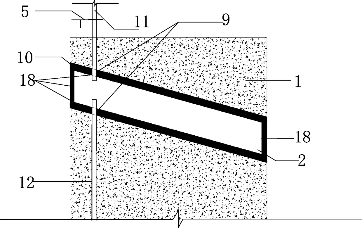
[0037] As shown in the figure, a geothermal collection device used in an underground diaphragm wall includes an underground diaphragm wall 1, a heat pipe 4, a main water inlet pipe 7, a main water outlet pipe 8, and an anchor steel pipe 13. The underground diaphragm wall 1 is provided with a water inlet Branch pipe 11, water outlet branch pipe 12 and heat conduction pipe 4, one end of water inlet branch pipe 11 is connected with heat conduction pipe 4, the other end is connected with main water inlet pipe 7, the end of heat conduction pipe 4 not connected with water inlet branch pipe 11 is connected with one end of water outlet branch pipe 12, The other end of the water outlet branch pipe 12 is connected to the main water outlet pipe 8, and the water inlet branch pipe 11, the water outlet branch pipe 12 and the heat conduction pipe 4 are connected to form a pipeline loop. The underground diaphragm wall 1 is multi-piece, and each underground diaphragm wall 1 is provided with a pi...


PUM


Abstract

A terrestrial heat collecting device used in the underground diaphragm walls comprises the underground diaphragm walls, heat conduction pipes, a main water inlet pipe, a main water outlet pipe and anchoring steel pipes. A water inlet branch pipe, a water outlet branch pipe and the corresponding heat conduction pipe are arranged in each underground diaphragm wall, wherein one end of the water inletbranch pipe is connected with the heat conduction pipe, and the other end of the water inlet branch pipe is connected with the main water inlet pipe; and the end, not connected with the water inlet branch pipe, of the heat conduction pipe is connected with one end of the water outlet branch pipe, the other end of the water outlet branch pipe is connected with the main water outlet pipe, and the water inlet branch pipe, the water outlet branch pipe and the heat conduction pipe are connected to form one pipeline loop. The multiple underground diaphragm walls are arranged. The corresponding pipeline loop is arranged in each underground diaphragm wall, the multiple pipeline loops are connected to the same main water inlet pipe and the same main water outlet pipe in parallel, and the main water inlet pipe and the main water outlet pipe are connected with a heat collector. By adoption of the above structure, the land area occupied by the terrestrial heat collecting device can be utilized tothe maximum degree, cost input is reduced, the terrestrial heat resource utilization efficiency can be effectively improved, and meanwhile stability and safety of the underground diaphragm walls areguaranteed.

Description

technical field [0001] The invention relates to the field of geothermal heating construction, in particular to a geothermal collection device used in an underground continuous wall. Background technique [0002] Geothermal resource is a kind of renewable energy that mostly comes from the depths of the earth, and exists in the form of thermal energy. It has a wide distribution range. If it can be developed and utilized reasonably, its economic benefits will be high. Today, as resource utilization continues to increase, it is very necessary to develop and utilize geothermal energy, and ground source heat pump technology was born. Ground source heat pump technology is a heating and cooling technology that uses shallow underground heat sources, which can reach The role of cooling in summer and heating in winter, the United States, Canada and some European countries have done in-depth research on geothermal pump technology and achieved remarkable results. However, the current deve...

Claims


Application Information

Patent Timeline
Patent Type & Authority Applications(China)
IPC IPC(8): F24T10/15
CPCY02E10/10
Inventor 邓华锋张伟强张永博李梦雪汪李洋曹中山刘文杰庞杰
Owner CHINA THREE GORGES UNIV
Why Eureka
Try Eureka