Calculation method for cutter torque of composite shield machine in rock and soil mixing geology tunneling

A technology of cutter head torque and calculation method, which is applied in calculation, special data processing applications, instruments, etc., can solve problems such as the friction torque of mixed geology without considering the geology, and achieve the effect of accurate and reliable calculation results.

Active Publication Date: 2018-07-03
TIANJIN UNIV
View PDF4 Cites 9 Cited by
  • Summary
  • Abstract
  • Description
  • Claims
  • Application Information

AI Technical Summary

Problems solved by technology

[0004] At present, the existing research on the cutter head torque mainly includes: 1. The calculation method of the cutter head torque of the tunnel boring machine in the excavation of the soft soil stratum; When the hob breaks the rock to generate torque, the frictional torque generated by the rock-soil mixture on the front and side of the cutterhead is not considered, that is, the torque of the entire cutterhead is not studied; 3. The composite earth pressure balance shield machine is analyzed in rock In soil mixed geology, the torque generated by cutter cutting soil and hob breaking rock, but when analyzing the frictional torque between the front, side and rock and soil of the cutterhead, th

Method used


Image

  • Calculation method for cutter torque of composite shield machine in rock and soil mixing geology tunneling
  • Calculation method for cutter torque of composite shield machine in rock and soil mixing geology tunneling
  • Calculation method for cutter torque of composite shield machine in rock and soil mixing geology tunneling

Examples


Embodiment Construction

[0039] The calculation method of the cutter head torque of the composite earth pressure balance shield of the present invention in rock-soil mixed geological excavation will be described in detail below in conjunction with the embodiments and the drawings.

[0040] The method for calculating the torque of the cutter head of the composite earth pressure balance shield in rock-soil mixed geological tunneling of the present invention includes the following steps:

[0041] 1) Calculate the torques as follows:,

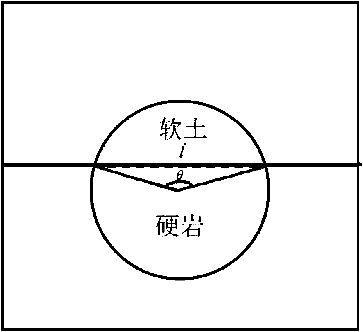
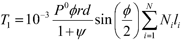
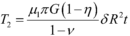
[0042] Torque T generated by the hob breaking rock 1 , The contact part of the cutter head panel and the soft soil layer is squeezed by tunneling to produce friction torque T 2 , The friction torque T of the contact part between the cutter head panel and the soft soil layer caused by the buried depth of the overburden 3 , The stratum resistance torque T of the cutterhead cutting soil 4 , Friction torque T between the side of the cutter head and the soft soil 5 , Friction torque T ...


PUM


Abstract

The invention discloses a calculation method for the cutter torque of a composite soil pressure balanced shield machine in rock and soil mixing geology tunneling. The calculation method comprises thefollowing steps that: independently calculating the following torque: torque generated by hobbing cutter rock breaking, frictional resistance torque generated by the tunneling extrusion of a contact part of a cutter panel and a soft soil layer, frictional resistance torque generated by the covering burial depth of the contact part of the cutter panel and the soft soil layer, the stratum resistancetorque of a cutter cutting soil body, frictional resistance torque between the side surface of the cutter and soft soil, frictional resistance torque T6 between the side surface of the cutter and rock and the stirring resistance torque of a stirring arm in a soil cabin; and calculating the tunneling cutter torque. By use of the calculation method, the cutter torque of the composite soil pressurebalanced shield machine in the tunneling process of the rock and soil mixing geology can be quickly and accurately calculated, and a calculation result is accurate and reliable. In addition, torque parameters can be flexibly regulated according to the change of a geological condition and tunneling speed at any time, and a reliable data basis is provided for setting and regulating the cutter torqueparameters in real time in the design and construction process of the dynamical system of the composite soil pressure balanced shield machine equipment.

Description

Technical field [0001] The invention relates to a method for calculating the torque of a cutter head in a composite earth pressure balance shield. In particular, it relates to a method for calculating the torque of the cutter head of a composite earth pressure balance shield in the excavation of rock-soil mixed geology. Background technique [0002] The tunnel boring machine is a complex engineering equipment system that integrates mechanical, electrical, hydraulic, optical, and gas systems and can realize factory tunnel operations. The shield construction method is widely used in the construction of large tunnel projects such as underground transportation and various transportation pipelines due to its advantages of small disturbance to the surrounding environment and high operation efficiency. [0003] According to the different ground conditions and specific construction methods, tunnel boring machines can generally be divided into hard rock tunnel boring machine (TBM), soft so...

Claims


Application Information

Patent Timeline
IPC IPC(8): G06F17/50
CPCG06F30/17
Inventor 张茜齐文聪亢一澜周思阳
Owner TIANJIN UNIV
Why Eureka
Try Eureka