Dynamic random access memory

A technology of dynamic random access and memory, applied in the field of semiconductors, can solve problems such as errors, achieve the effect of reducing soft errors and increasing manufacturing costs

Active Publication Date: 2018-07-03
UNITED MICROELECTRONICS CORP +1
View PDF6 Cites 0 Cited by
  • Summary
  • Abstract
  • Description
  • Claims
  • Application Information

AI Technical Summary

Problems solved by technology

Redundant circuits generally contain latch elements, but the latched data may also have errors

Method used


Image

  • Dynamic random access memory
  • Dynamic random access memory
  • Dynamic random access memory

Examples


Embodiment Construction

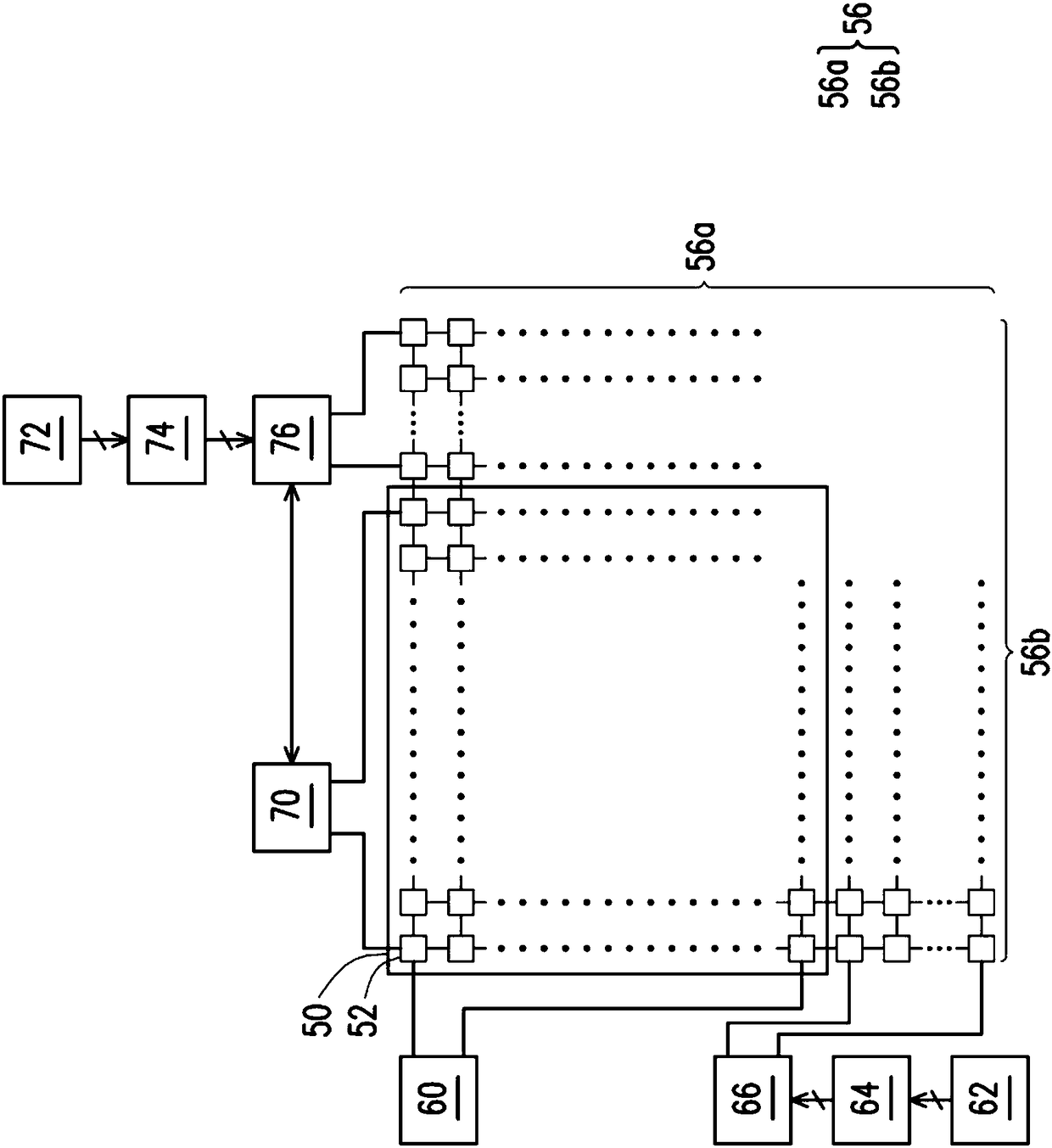
[0029] Generally, the architecture of a Dynamic Random Access Memory (DRAM) includes a main block composed of a memory cell array, and also includes redundant element units. The redundant element unit generally includes a plurality of redundant memory cells (redundant cells), a decoder (decoder), a fuse (e-fuse), and a latch (latch) and other blocks. For the plurality of memory cells of the memory cell array of the main block, for example, after the manufacturing is completed or any time to be tested, the test procedure will be started. After testing, when it is found that at least one memory cell cannot store data correctly, these memory cells are regarded as damaged memory cells (defective cell(s)), and their data addresses will use fuses to store the corresponding row address and column address. When the dynamic random access memory is in normal use, the address information stored in the fuse will be downloaded to the latch block, and then the decoder will activate the cor...


PUM


Abstract

The invention relates to a dynamic random access memory which comprises a main memory cell array and a redundant element unit. The redundant element unit contains multiple fuse wires and a latching area. The multiple fuse wires are planned to be a first fuse wire part and a second fuse wire part, wherein the first fuse wire part is used for storing address information of a fault memory cell in themain memory cell array and the second fuse wire part is used as multiple capacitors. The latching area contains multiple latches which are used for storing the address information of the fault memorycell stored in the first fuse wire part, wherein the multiple capacitors of the second fuse wire part are respectively coupled to the multiple latches, so as to provide capacitance to the output / input (I / O) endpoint of each of the latches.

Description

technical field [0001] The present invention relates to semiconductor technology. More particularly, the present invention relates to dynamic random access memory. Background technique [0002] DRAM is a very common memory, such as applied in smart electronic devices, which is beneficial to quickly perform the actions to be processed. As the functions of smart electronic devices become more and more powerful, the capacity of the required DRAM increases accordingly. Coupled with the trend of size reduction, the density of memory cells also increases. [0003] Under such requirements, for the manufacture of dynamic random access memory, it is difficult to achieve that every memory cell in the memory cell array is not damaged, and therefore, dynamic random access memory will have redundant components in addition to the main memory cell array unit. After the DRAM is manufactured, each memory cell of the main memory cell array needs to be tested, wherein the damaged memory cel...

Claims


Application Information

Patent Timeline
Patent Type & Authority Applications(China)
IPC IPC(8): G11C29/00
CPCG11C29/787G11C29/816G11C29/789G11C11/408G11C11/4096G11C11/4087
Inventor 永井享浩
Owner UNITED MICROELECTRONICS CORP
Why Eureka
Try Eureka