Conical disc rack of disc centrifugal machine

A disc centrifuge and disc technology, applied in centrifuges and other directions, can solve problems such as reducing the separation efficiency of disc centrifuges

Inactive Publication Date: 2018-07-06
CHANGZHOU UNIV
View PDF4 Cites 4 Cited by
  • Summary
  • Abstract
  • Description
  • Claims
  • Application Information

AI Technical Summary

Problems solved by technology

This will reduce the separation efficiency of the disc centrifuge, and one of the main reasons for this flow phenomenon is that the gap between the inner diameter of the disc and the disc holder is the same up and down

Method used


Image

  • Conical disc rack of disc centrifugal machine

Examples


Embodiment 1

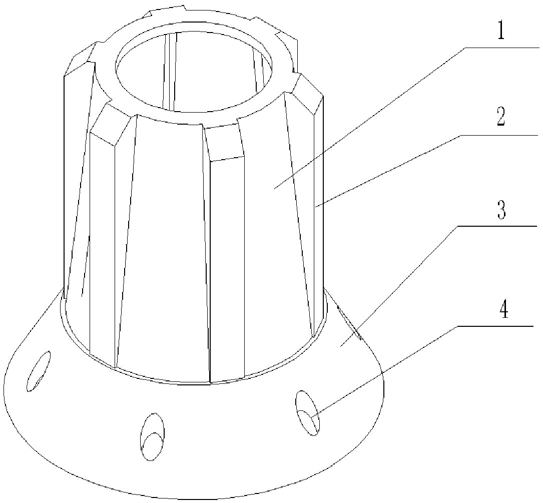
[0019] like figure 1 Shown: When the present invention is used with the disc set, the material containing the mixture of light and heavy phases enters the disc gap, the heavy phase is thrown to the drum wall under the action of centrifugal force, and the light phase flows to the axial direction of the disc frame. As the volume of the light phase channel gradually increases, the distribution of fluid pressure in the gap between the bottom layer and the upper layer disc is improved, so that the fluid distribution in each layer tends to be uniform, and the separation effect of the disc centrifuge is improved.

[0020] The invention increases the volume in the flow channel by controlling the cross-sectional area of ​​the light-phase fluid flow channel from small to large, and changes the structure of the disc frame of the disc centrifuge to change the pressure of the fluid in the gap between the inner diameter of the disc and the disc frame Therefore, the fluid flow in the disc ga...


PUM


Abstract

The invention discloses a conical disc rack of a disc centrifugal machine. The conical disc rack of the disc centrifugal machine comprises a conical disc rack body, positioning boards, a disc and neutral holes, and is characterized in that the conical disc rack body (1) is conical, the ring diameter of the conical disc rack body is gradually decreased from bottom to top, and the conical disc rackis formed. Materials pass through the neutral holes (4), are separated by the disc (3), and flow out between the positioning boards (2). By controlling the cross section area of a light-phase fluid runner to be gradually increased, the volume in the runner is increased, the inner diameter of the disc and the pressure distribution of fluid in the interval of the disc rack are changed, accordingly flowing of the fluid in the interval of layers of discs is improved, distribution of the fluid in the interval of the layers of discs tends to be uniform, and thus the purpose of improving the separation efficiency is achieved.

Description

technical field [0001] The invention relates to a separation machine in the technical field of centrifugal separation, in particular to a separation machine structure with high separation precision and simple assembly. Background technique [0002] Disc centrifuges are widely used and are very common in industrial production, such as: chemical, pharmaceutical, food, transportation, light industry and biological industries. Its function is to purify dispersed materials, recycle dispersed materials, protect subsequent equipment, and mainly purify, classify, and classify materials. As one of the core parts in the drum of the disc centrifuge, the disc holder directly contacts the material, participates in the separation process and the process of discharging after separation, which has an important impact on the separation effect and separation efficiency of the separator. [0003] In the actual production of the disc centrifuge, the material is unevenly distributed in the gap ...

Claims


Application Information

Patent Timeline
Patent Type & Authority Applications(China)
IPC IPC(8): B04B7/12
CPCB04B7/12
Inventor 付双成朱杭张宇恒缪文婧袁惠新
Owner CHANGZHOU UNIV
Why Eureka
Try Eureka