Transmission gear burr removal device

A transmission gear and deburring technology, which is applied in the field of gear processing, can solve problems such as inability to remove burrs at positioning sleeve holes, incomplete deburring, and uneven processing, so as to overcome incomplete deburring and improve the effect of deburring , to achieve the effect of automatic control

Inactive Publication Date: 2018-07-06
NINGBO HAIMAN AUTOMOTIVE TECH CO LTD
View PDF12 Cites 3 Cited by
  • Summary
  • Abstract
  • Description
  • Claims
  • Application Information

AI Technical Summary

Problems solved by technology

[0004] Although the above-mentioned patented scheme can remove the burrs in the inner hole of the gear, there are still some deficiencies in this scheme: 1. When in use, the positioning sleeve is first positioned in the hole to be deburred, and then deburred by a bayonet knife. Under normal circumstances, the burr knife cannot remove the burr on the hole of the positioning sleeve, resulting in incomplete deburring; 2. When in use, it is necessary to manually pull the pull ring to push the push rod, so that the burr knife moves back and forth to remove the burr in the inner hole of the gear. Removal, manual operation is not only inefficient, but also easy to cause uneven processing

Method used


Image

  • Transmission gear burr removal device

Examples


Embodiment Construction

[0019] The present invention will be described in further detail below by means of specific embodiments:

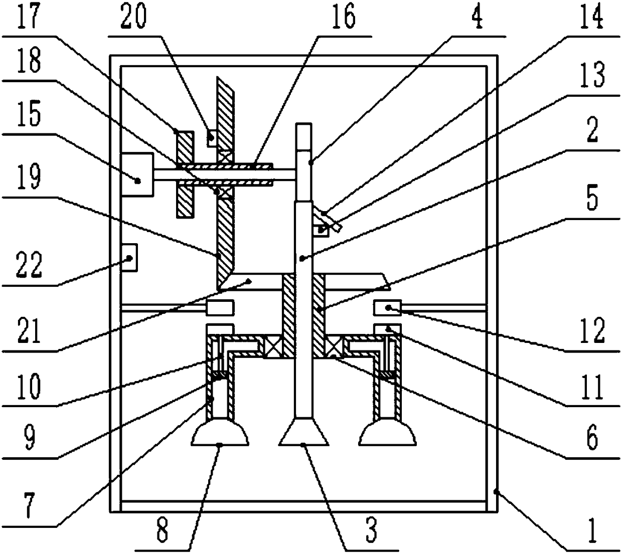
[0020] The reference signs in the drawings of the description include: frame 1, rotating shaft 2, burr knife 3, cam 4, inner ring 5, bearing 6, piston cylinder 7, suction cup 8, piston 9, piston rod 10, first electromagnet 11. Second electromagnet 12, touch switch 13, swing rod 14, motor 15, sleeve 16, permanent magnet 17, rolling bearing 18, first bevel gear 19, third electromagnet 20, second bevel gear 21, manual switch 22.

[0021] This embodiment is basically as attached figure 1 Shown:

[0022] The transmission gear deburring device includes a frame 1, a rotating shaft 2 is slidingly connected to the frame 1, the lower end of the rotating shaft 2 is connected with a deburring knife 3 through screws, and a cam 4 is arranged at the upper end of the rotating shaft 2, and the rotating shaft 2 and the frame 1 A spring is welded between the top walls, an inner ring 5 is...


PUM


Abstract

The invention relates to the technical field of gear machining, and discloses a transmission gear burr removal device. The device comprises a rack, a rotating shaft is in sliding connection to the rack, a burr knife is arranged at one end of the rotating shaft, a cam is arranged on the other end of the rotating shaft in an abutting manner, a spring is connected between the rotating shaft and the top wall of the rack, the rotating shaft is sleeved with an inner ring in a spline manner, the inner ring is rotatably sleeved with an outer ring, two piston cylinders are fixed to the outer ring, andare located on the two sides of the rotating shaft correspondingly, the free end of each piston cylinder is communicated with a suctin cup used for postioning a workpiece, a piston is in sliding connection into each piston cylinder, a piston rod is fixed to each piston, a first electromagnet is fixed to each piston rod, each first electromagnet abuts against the outer wall of the corresponding piston cylinder, a second electromagnet opposite to the first electromagnet in polarity is arranged on the rack, a touch switch is fixed to the rotating shaft, and a swing rod used for starting and stopping the touch switch is hinged to the rotating shaft. A workpiece can be accurately positioned and automatically machined, and machining accuracy and efficiency can be improved.

Description

technical field [0001] The invention relates to the technical field of gear processing, in particular to a transmission gear deburring device. Background technique [0002] The gear is an indispensable part in the automobile transmission. The gear and the transmission shaft are connected by threads, so a connecting hole is drilled on the outer circle of the gear. Directional flanging, because the inner hole and the transmission shaft are very precise, if there is flanging, the gear will not be able to be assembled, thus making the gear unusable. [0003] In order to solve the above problems, Chinese patent (CN104722847B) discloses a deburring device for automotive gears, including a mounting base, including a motor, a bearing, a rotating shaft, a positioning sleeve, a push rod, a deburring knife, and a pull ring. The motor is located in the center of the mounting base. The two are connected by threads, the bearing is located at the center of the right end of the mounting se...

Claims


Application Information

Patent Timeline
Patent Type & Authority Applications(China)
IPC IPC(8): B23D79/00B23Q3/08
CPCB23D79/00B23Q3/088
Inventor 项文增
Owner NINGBO HAIMAN AUTOMOTIVE TECH CO LTD
Why Eureka
Try Eureka