Supercharge Your Innovation With Domain-Expert AI Agents!

Beveling feed adjusting mechanism

An adjustment mechanism and material feeding technology, which can be used in thin material processing, metal processing, winding strips, etc., can solve problems such as poor feeding, excessive waste, and low efficiency, and achieve smooth feeding and prevent material jamming

Pending Publication Date: 2018-07-06
JINHUA SHENGCHANG MACHINERY
View PDF0 Cites 0 Cited by
  • Summary
  • Abstract
  • Description
  • Claims
  • Application Information

AI Technical Summary

Problems solved by technology

[0002] In order to feed smoothly and facilitate cutting, the feeding roller and feeding spring of the slitting machine on the existing market are as close as possible to the cutting knife. This design has caused the problem that the existing slitting machine cannot be inclined, because if it is to be inclined It is necessary to adjust the scissors to form an oblique angle with the paper material. At this time, the feeding roller and the feeding spring will be farther away from the shearing knife than when cutting across, resulting in poor feeding and cannot be processed.
At present, paper with missing corners is generally cut crosswise first and then obliquely. The efficiency is low, the labor is increased, and too much waste is generated. Therefore, there is an urgent need in the market for a feeding adjustment structure that can be installed on the slitting machine to achieve the oblique cutting effect.

Method used


Image

  • Beveling feed adjusting mechanism
  • Beveling feed adjusting mechanism
  • Beveling feed adjusting mechanism

Examples


Embodiment Construction

[0014] Hereinafter, the present invention will be described in detail with reference to the drawings and examples. It should be noted that, in the case of no conflict, the embodiments in the present application and the features in the embodiments can be combined with each other.

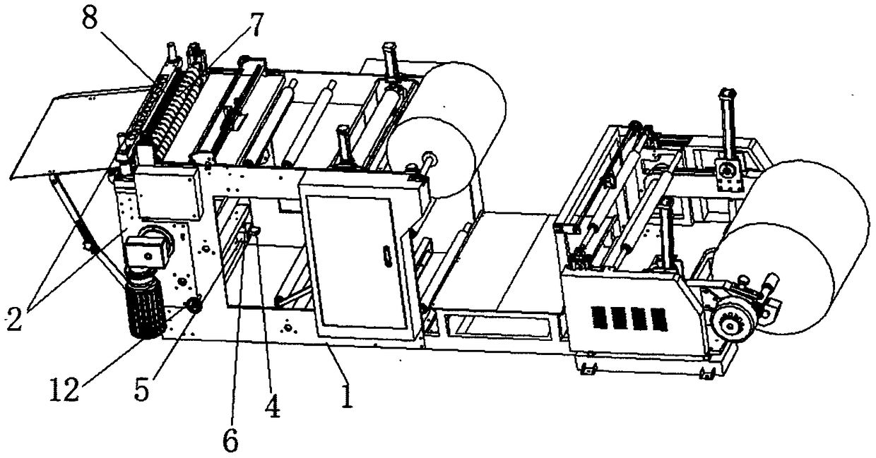
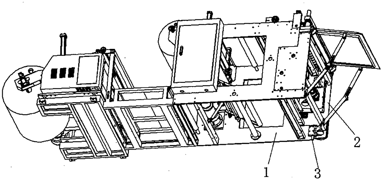
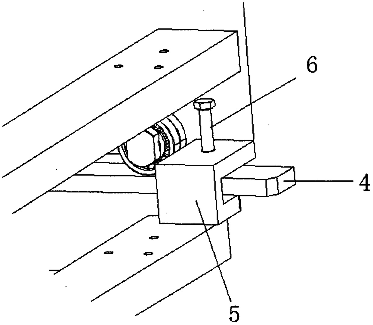
[0015] Such as figure 1 As shown, according to the embodiment of the present invention, the bevel feed adjustment mechanism includes: frame 1, frame 1 is fixed with cutting knife rest 2, roller frame 8 and feeding roller 7 successively from left to right, and above-mentioned cutting knife rest 2 is fixed On the leftmost side of frame 1, fixed by hinge 3 (refer to figure 2 ,From figure 2 We can see that the folding leaf 3 is fixed on the inner bottom side of the frame 1 and the folding knife rest 2), so that the cutting knife rest 2 can change at a certain angle along one direction, combined with image 3 Explain that the above-mentioned roller frame 8 is fixed on the top of the right side of the...


PUM


Abstract

The invention provides a beveling feed adjusting mechanism. The beveling feed adjusting mechanism comprises a rack. A cutting knife rest is connected to one side edge of the rack through a folding hinge and achieves angle adjusting through the folding hinge, and a splitting machine can achieve the beveling effect. To fix the adjusted angle, a bolt plate lock and a bolt plate are fixed to the rackand the cutting knife rest correspondingly, a bolt penetrates through the bolt plate lock to fix the bolt plate in the bolt plate lock, and therefore the cutting knife rest connected with the bolt plate can also be fixed. To facilitate paper conveying, feed rollers are fixed to the rack, a rolling wheel shelf is fixed to the side, opposite to the feed rollers, of the cutting knife rest, multiple rolling wheel sets are fixed to the rolling wheel shelf, and a steering rod of each universal wheel in the rolling wheel sets penetrates through a strip-shaped hole in the rolling wheel shelf and is fixed with a nut. Therefore, after the angle of the cutting knife rest is adjusted, feed springs wound between the universal wheels and the feed rollers can be in a parallel state by adjusting the positions of the universal wheels, and feed of the two feed rollers is quite smooth.

Description

technical field [0001] The invention relates to a slitting machine accessory, in particular to a slitting machine oblique feeding adjustment mechanism. Background technique [0002] In order to feed smoothly and facilitate cutting, the feeding roller and feeding spring of the slitting machine on the existing market are as close as possible to the cutting knife. This design has caused the problem that the existing slitting machine cannot be inclined, because if it is to be inclined It is necessary to adjust the scissors to form an oblique angle with the paper material. At this time, the feeding roller and the feeding spring will be farther away from the shearing knife than when cutting across, resulting in poor feeding and cannot be processed. At present, paper with missing corners is generally cut crosswise first and then obliquely. The efficiency is low, the labor is increased, and too much waste is generated. Therefore, there is an urgent need in the market for a feeding a...

Claims


Application Information

Patent Timeline
Patent Type & Authority Applications(China)
IPC IPC(8): B26D3/02B26D7/26B65H20/02
CPCB65H20/02B26D3/02B26D7/2628
Inventor 张向阳张方向
Owner JINHUA SHENGCHANG MACHINERY
Features
  • R&D
  • Intellectual Property
  • Life Sciences
  • Materials
  • Tech Scout
  • Unparalleled Data Quality
  • Higher Quality Content
  • 60% Fewer Hallucinations
Learn More