Novel die cutting machine fixture

A die-cutting machine and fixture technology, applied in metal processing, etc., can solve the problems of complex operation, waste of production time, large manpower and material resources, etc., and achieve the effect of increasing cutting speed, speeding up work efficiency, and increasing sources

Inactive Publication Date: 2018-07-06
孙柳英
View PDF0 Cites 1 Cited by
  • Summary
  • Abstract
  • Description
  • Claims
  • Application Information

AI Technical Summary

Problems solved by technology

[0003] According to the needs of the use, the mold plate needs to be switched according to the function to adapt to different processes, such as die-cutting mold plate, bronzing mold plate, embossing mold plate, etc. However, to replace the mold plate, it needs to be replaced together with the fixture above it, the operation is complicated and wasteful Production time, manpower and material resources are required, so a multi-fit die-cutting machine fixture is what people need

Method used


Image

  • Novel die cutting machine fixture
  • Novel die cutting machine fixture
  • Novel die cutting machine fixture

Examples


Embodiment Construction

[0021] In order to further understand the invention content, characteristics and effects of the present invention, the following embodiments are listed below, and detailed descriptions are as follows in conjunction with the accompanying drawings.

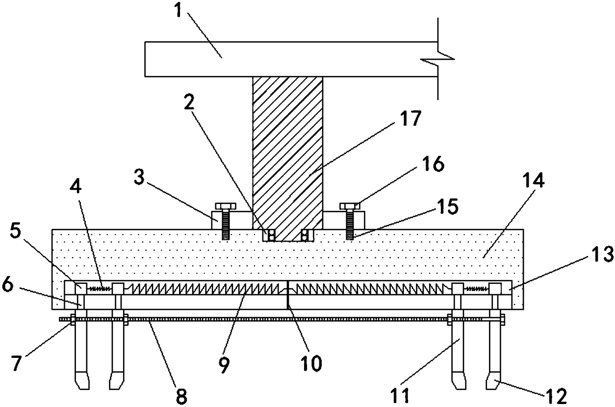
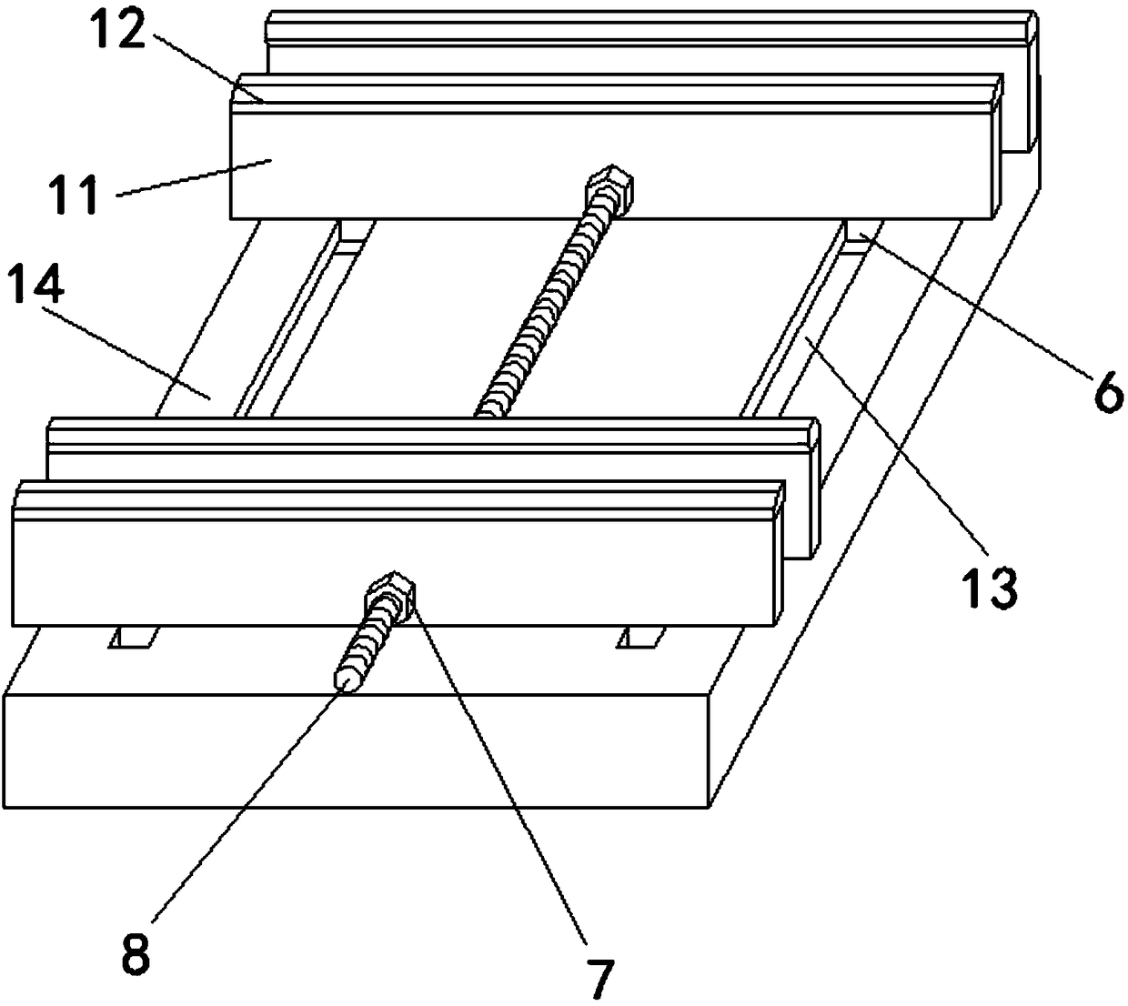
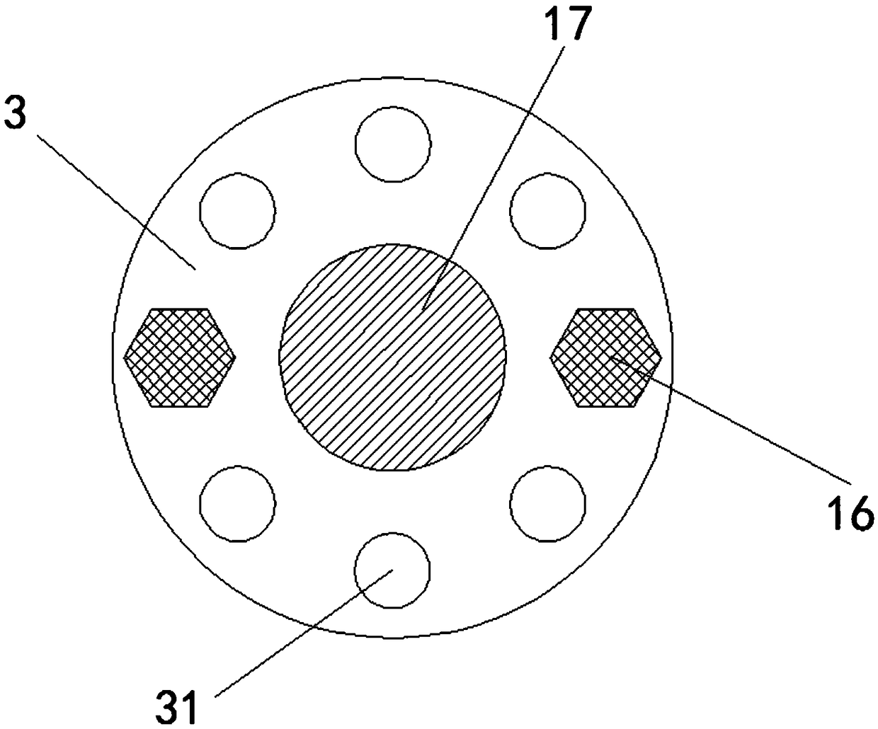
[0022] Combine below Figure 1-3 A detailed description of the new die-cutting machine clamp of the present invention: a new die-cutting machine clamp includes a pressure bearing plate 1, an adjusting flange 3, a splint 11, a clamping head 12, a clamp body 14 and a connecting rod 17. A vertical connecting rod 17 is fixed below the pressure bearing plate 1, and the lower end of the connecting rod 17 is covered with an adjusting flange 3, and the adjusting flange 3 is fixedly connected with the connecting rod 17, and the upper end of the adjusting flange 3 A number of evenly distributed adjusting holes 31 are arranged around the connecting rod 17, wherein two adjusting holes 31 symmetrical to the connecting rod 17 are provided with li...


PUM


Abstract

The invention relates to a novel die cutting machine fixture. The novel die cutting machine fixture comprises a pressure bearing plate, an adjustable flange plate, clamping plates, clamping heads, a fixture main body and a connecting rod; the vertical connecting rod is fixed below the pressure bearing plate; the adjustable flange plate sleeves the lower end of the connecting rod; four clamping plates capable of moving in chutes are arranged below the fixture main body; gaps between the clamping plates are adjusted through springs and nuts on screw rods; outer side clamping areas connected by first springs can be used for clamping such mold plates as cutters with smaller widths, and a middle clamping area connected by second springs can be used for clamping such mold plates as gold stampingmold plates and belled mold plates with larger sizes, so that the applicability of the device is widened, the condition of replacing the fixture at the same time when molds are replaced is prevented,the operation is more convenient, and a lot of manpower and working time are saved; and meanwhile, the two outer side clamping areas can be singly used, and the other one is for future use or can beused at the same time for cutting such materials as paper with equal gaps, so that the working efficiency is improved.

Description

technical field [0001] The invention belongs to the technical field of die-cutting machines, and in particular relates to a novel die-cutting machine clamp. Background technique [0002] Die-cutting machine is mainly used for die-cutting, indentation and cold embossing operations of trademarks, cartons, greeting cards, etc. in the paper packaging and decoration industry. It is an important equipment for post-press packaging processing and molding. Types of die-cutting machines According to different embossing forms, it is mainly divided into three types: circular pressing, round pressing and flat pressing. According to the form of template placement, it can be divided into two types: vertical type and horizontal type. In addition, there is also a hot stamping function, called a hot stamping die-cutting machine, and some with an automatic waste removal function, called a waste-removing die-cutting machine. High efficiency, it can be connected with offset printing machine, fl...

Claims


Application Information

Patent Timeline
IPC IPC(8): B26F1/44
CPCB26F1/44B26F2001/4463
Inventor 孙柳英
Owner 孙柳英
Why Eureka
Try Eureka