Rotor wing flight mechanical arm system and algorithm based on dynamic gravity center compensation

A rotorcraft and robotic arm technology, applied in the field of rotorcraft manipulator systems and flying robots, can solve problems such as insufficient consideration of the coupling and interference between the robotic arm and the rotorcraft, the lack of stability in the grasping operation, and the inability to complete the grasping, etc. Achieve the effect of improving the efficiency of grasping time, improving the performance of attitude control, and improving the accuracy rate

Inactive Publication Date: 2018-07-06
HUNAN UNIV
View PDF10 Cites 31 Cited by
  • Summary
  • Abstract
  • Description
  • Claims
  • Application Information

AI Technical Summary

Problems solved by technology

Although the degree of freedom of the mechanical arm described in this invention is increased and has sufficient flexibility, it only improves the structure without fully considering the coupling and interference between the mechanical arm and the rotorcraft, and lacks stability in the grasping operation. It is likely to lead to the failure of grasping. At the same time, only relying on manual positioning to achieve grasping generally requires multiple trials, which is inefficient, and the grasping cannot be completed when the target is far away from the operator

Method used


Image

  • Rotor wing flight mechanical arm system and algorithm based on dynamic gravity center compensation
  • Rotor wing flight mechanical arm system and algorithm based on dynamic gravity center compensation
  • Rotor wing flight mechanical arm system and algorithm based on dynamic gravity center compensation

Examples


Embodiment

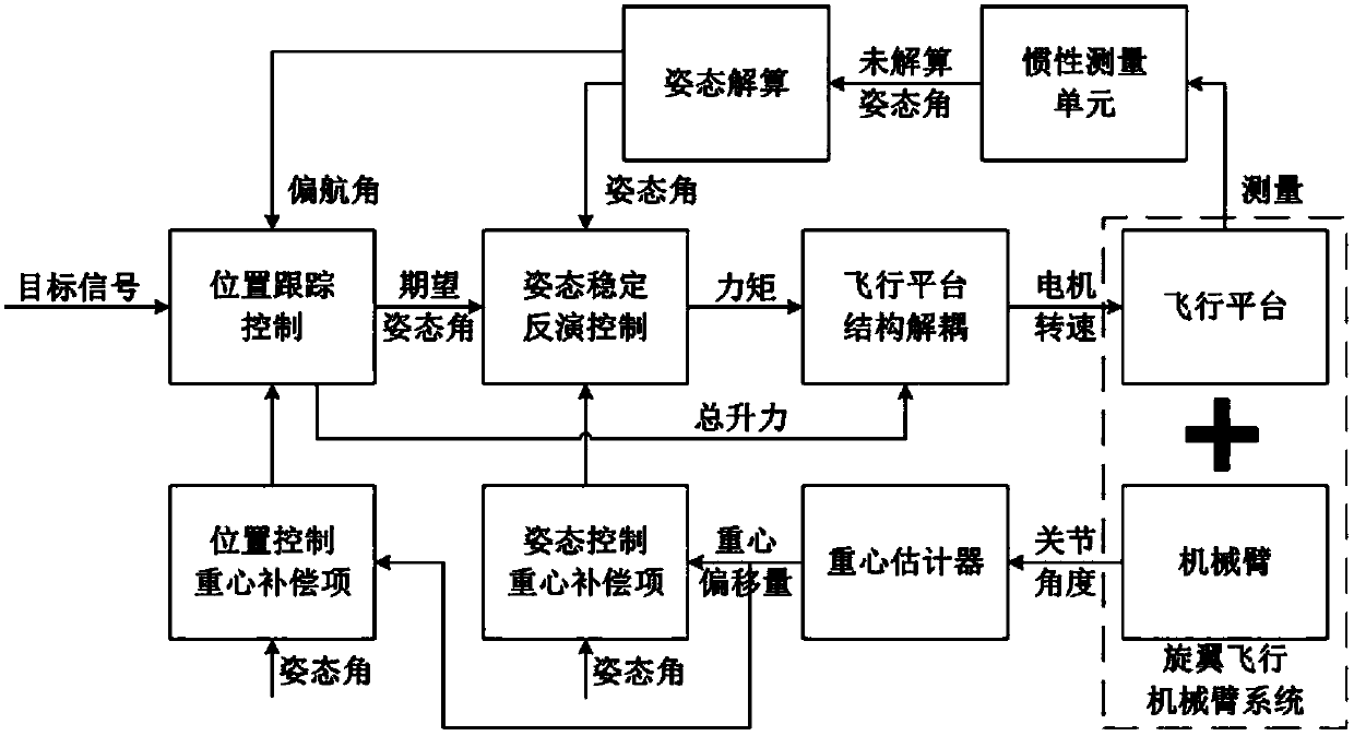
[0053] The attitude control block diagram of a rotor flying manipulator system with dynamic center of gravity compensation algorithm is as follows: image 3 shown, including the following steps:

[0054] (1) Data reading, including the position and attitude information of the rotorcraft and the angles of the joints of the mechanical arm;

[0055] (2) Estimation of the center of gravity of the system;

[0056] Such as image 3 , to estimate the vector r of the center of gravity of the system in the body coordinate system {B} G =[x G ,y G ,z G ] T , each joint angle θ transmitted by the manipulator system to the system controller i , to obtain the coordinate system J of the center of mass of the articulated arm i relative to the articulated arm i i The local coordinates of Respectively represent the joint arm i coordinate system J i The rotation transformation matrix and position coordinates relative to the flight platform coordinate system {B}. The position coordina...


PUM


Abstract

The invention discloses a rotor wing flight mechanical arm system and algorithm based on dynamic gravity center compensation. The system comprises a rotor wing flight platform, an image sensor, a connecting frame, a mechanical arm system, a system controller and a ground station control device. The rotor wing flight platform comprises a rotor wing aircraft and a flight controller. The image sensoris installed below the front part of the rotor wing flight platform. The connecting frame is a mechanical plate which is used for fixedly connecting the rotor wing flight platform, the image sensor and the mechanical arm system. The mechanical arm system is installed just below the rotor wing flight platform. The system controller is installed right above the rotor wing flight platform. The ground station control device is communicated with the system controller in a wireless mode. The system is rational in structural design, high in safety, and strong in stability. The algorithm is capable of improving the accuracy rate of capturing, and improving the time efficiency of capturing.

Description

technical field [0001] The invention belongs to the technical field of robot design and control, relates to a flying robot, in particular to a rotor flying manipulator system and algorithm based on dynamic center of gravity compensation. Background technique [0002] With the rapid development of ground mobile robot technology, breakthroughs have been made in the research of unmanned aerial vehicles. Because of its small size, flexible operation, and hovering characteristics, it has been widely used in monitoring, map remote sensing, commercial aerial photography, and agricultural applications. It has a wide range of applications, but most of them are passive observations. With the continuous development of research technology, it is expected that flying robots can interact with the environment. With ground robots equipped with multi-degree-of-freedom manipulators, ground operation robots have been recognized and successfully applied in the fields of disaster relief and ant...

Claims


Application Information

Patent Timeline
Patent Type & Authority Applications(China)
IPC IPC(8): B64C27/08B64D47/00B25J9/08
CPCB64C27/08B25J9/08B64D47/00
Inventor 谭建豪刘芯钟杭王耀南李希韩奇孙敬陶李瑞涵罗琼华
Owner HUNAN UNIV
Why Eureka
Try Eureka