
A shape-controllable top-layer foil heat treatment tool for elastic foil bearings

A technology of elastic foil and tooling, applied in heat treatment furnaces, heat treatment equipment, manufacturing tools, etc., can solve the problems of reducing foil corrosion resistance and mechanical fatigue performance, increasing processing costs, foil scrapping, etc., to curb the degree of surface oxidation , prevent surface oxidation, good bonding effect

Active Publication Date: 2019-04-16
XI AN JIAOTONG UNIV
View PDF10 Cites 0 Cited by
  • Summary
  • Abstract
  • Description
  • Claims
  • Application Information

AI Technical Summary

Problems solved by technology

For thinner top layer foils, irregular thermal deformation is prone to occur during heat treatment, resulting in foil scrapping
At the same time, foils are generally made of high-temperature alloys, which require a higher heat treatment temperature to achieve the predetermined mechanical properties. In the commonly used high-temperature alloy heat treatment heat treatment process, the peak temperature is nearly 1000 ° C, and research shows that some high-temperature alloys are heated to 500 More obvious surface oxidation will occur when the temperature is above ℃, so the oxidation problem in the heat treatment process cannot be ignored. Surface oxidation will greatly reduce the corrosion resistance and mechanical fatigue properties of the foil, so heat treatment with excellent vacuum degree is required. Furnace to operate, which will greatly increase the processing cost

Method used


Image

  • A shape-controllable top-layer foil heat treatment tool for elastic foil bearings
  • A shape-controllable top-layer foil heat treatment tool for elastic foil bearings
  • A shape-controllable top-layer foil heat treatment tool for elastic foil bearings

Examples


Embodiment Construction

[0016] The present invention will be described in further detail below in conjunction with the accompanying drawings.

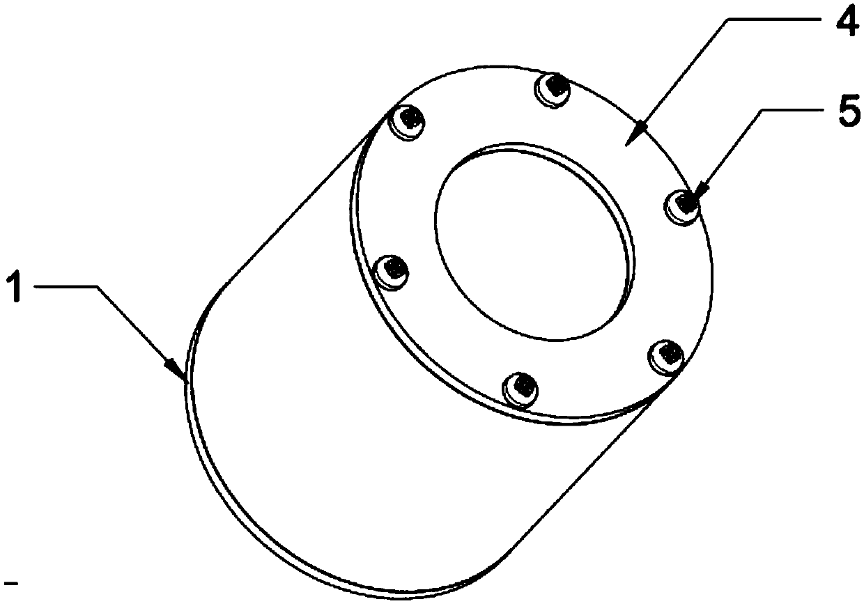
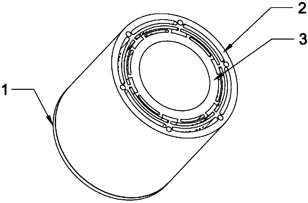
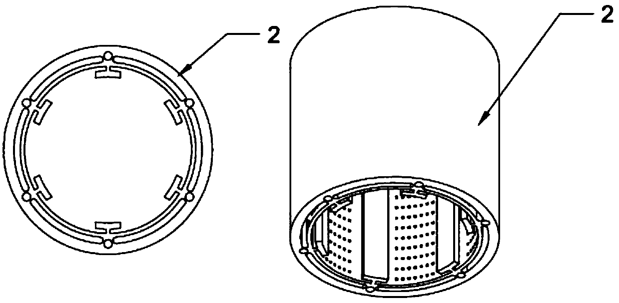
[0017] Such as figure 1 , figure 2 As shown, a controllable shape-controllable elastic foil bearing top layer foil heat treatment tooling includes an inner mold 3, and the inner mold 3 is loaded into the outer mold 2 through the slot matched with the outer mold 2, and forms with the outer mold 2 A plurality of through slots capable of placing elastic foils, the two ends of the inner mold 3 and the outer mold 2 are provided with a bottom cover 1 and a top cover 4, and the bottom cover 1 and the top cover 4 are fixed on the outer mold by fastening screws 5 2 above; during the heat treatment process, the elastic foil is inserted into the through groove formed by the outer mold 2 and the inner mold 3 to form a predetermined curvature, which can be fixed after the heat treatment to achieve the effect of shape control. The curvature radius of the through groove ...


PUM


Abstract

An elastic foil piece bearing top layer foil piece heat treatment tool capable of controlling the shape and performance comprises an inner mold which is loaded into an outer mold, a plurality of through grooves for allowing elastic foil pieces to be stored can be formed by the inner mold and the outer mold, and a bottom layer cover plate and a top layer cover plate arranged at the two ends of theinner mold and the outer mold are fixed to the outer mold through fastening bolts; in the heat treatment process, the elastic foil pieces are inserted into the through grooves formed by the outer moldand the inner mold, a preset curvature is formed, the curvature is fixed after heat treatment is conducted, and the effect of shape controlling is achieved; and the inner side of the outer mold and the outer side of the inner mold are provided with rectangular pit dot matrix in a manufactured mode, the ends of the outer mold and the inner mold are provided with through holes in a manufactured mode, and the through holes communicate with the rectangular pit dot matrix, and aluminum oxide powder added into the through holes makes contact with the elastic foil pieces through the rectangular pitdot matrix to reduce surface oxidation of the elastic foil pieces. The elastic foil piece bearing top layer foil piece heat treatment tool capable of controlling shape and performance can control heatdeformation of the foil pieces and meanwhile prevent surface oxidation of the foil pieces.

Description

technical field [0001] The invention belongs to the technical field of elastic foil bearings, and in particular relates to a shape-controllable top-layer foil heat treatment tool of an elastic foil bearing. Background technique [0002] During the manufacturing process of the elastic foil dynamic pressure gas bearing top layer foil, vacuum heat treatment is required to improve the elasticity and comprehensive physical and chemical properties of the foil. For thinner top layer foils, irregular thermal deformations are prone to occur during heat treatment, resulting in foil scrapping. At the same time, foils are generally made of high-temperature alloys, which require a higher heat treatment temperature to achieve the predetermined mechanical properties. In the commonly used high-temperature alloy heat treatment heat treatment process, the peak temperature is nearly 1000 ° C, and research shows that some high-temperature alloys are heated to 500 More obvious surface oxidation...

Claims


Application Information

Patent Timeline
Patent Type & Authority Patents(China)
IPC IPC(8): C21D9/46C21D1/74
CPCC21D1/74C21D9/46
Inventor 耿海鹏李昊吕浩唐思训齐垒周健虞烈
Owner XI AN JIAOTONG UNIV
Learn More