Installing structure of cable strand in multi-tower suspension bridge cable saddle

A technology for installing structures and suspension bridges, applied in bridges, bridge parts, bridge construction, etc., can solve the problems of driving comfort, ineffective improvement, unbalanced force of the main cable, etc. Slip safety, friction resistance improvement effect

Pending Publication Date: 2018-07-06
SOUTHWEST JIAOTONG UNIV
View PDF9 Cites 3 Cited by
  • Summary
  • Abstract
  • Description
  • Claims
  • Application Information

AI Technical Summary

Problems solved by technology

[0003] Suspension bridges have great competitive advantages when crossing wide waters. Multi-tower suspension bridges have great development prospects due to their super spanning ability, but the live load during operation is the most unfavorable state (one span is fully loaded and the other is empty) in the middle bridge tower A huge unbalanced force will be generated, which will cause a great unbalanced force on the main cables on both sides of the cable saddle at the middle tower, and the main cable will easily slip in the cable saddle, seriously threatening the structural safety of the multi-tower suspension bridge
The anti-slip safety between the saddle and the main cable of the multi-tower suspension bridge is one of the basic prerequisites to ensure the stress safety of the multi-tower suspension bridge system. In order to improve the anti-slip safety of the multi-tower suspension bridge, the methods adopted in the p

Method used


Image

  • Installing structure of cable strand in multi-tower suspension bridge cable saddle
  • Installing structure of cable strand in multi-tower suspension bridge cable saddle

Examples


Embodiment Construction

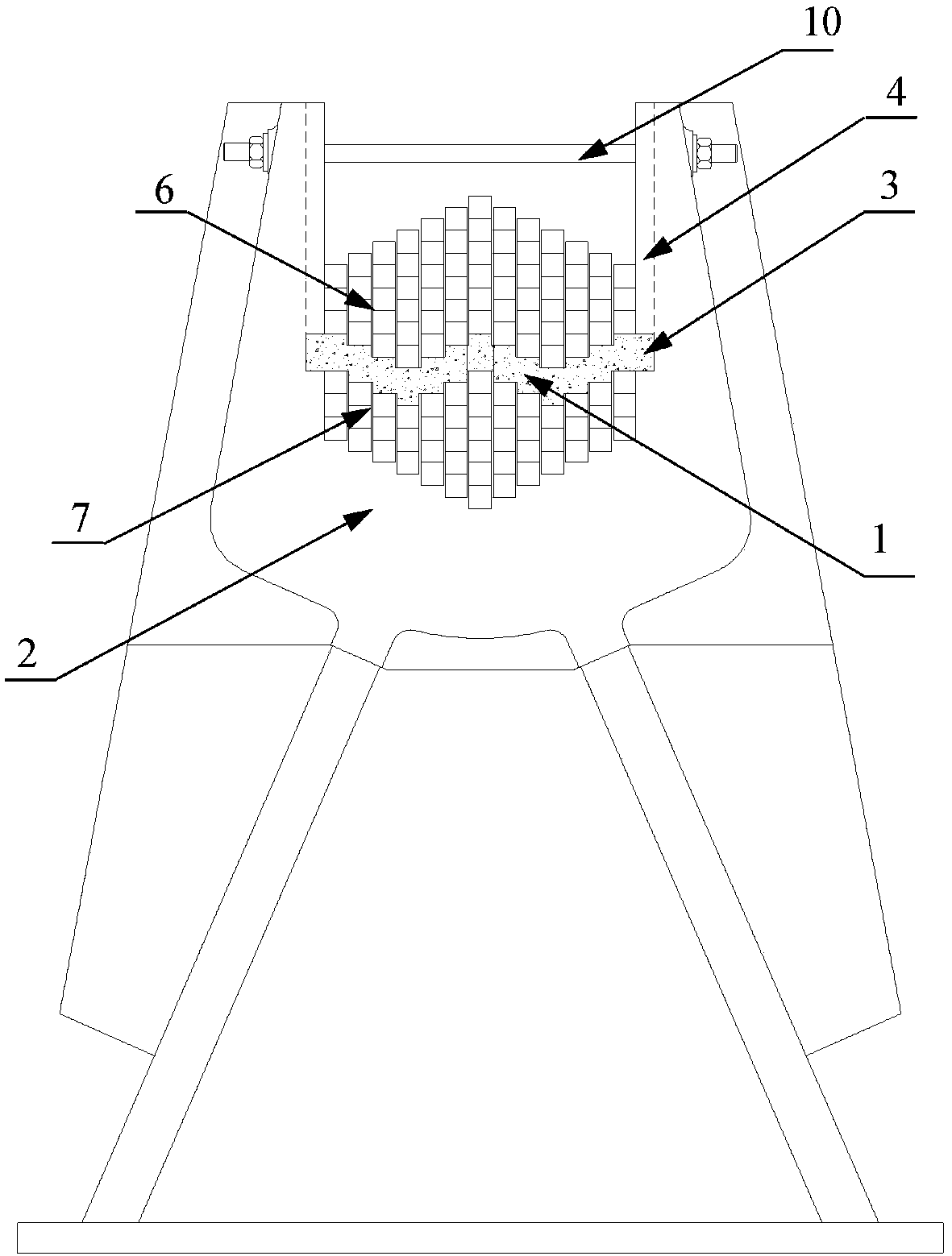
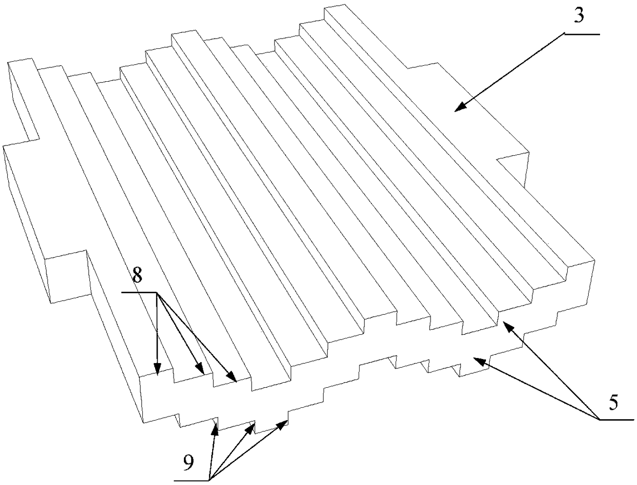
[0027] Those skilled in the art will be able to implement the present invention based on these descriptions. Before the present invention is described in conjunction with the accompanying drawings, it should be pointed out that:

[0028] The technical solutions and technical features provided in each part of the present invention, including the following description, can be combined with each other under the condition of no conflict.

[0029] In addition, the embodiments of the present invention referred to in the following description are generally only a part of the embodiments of the present invention, rather than all the embodiments. Therefore, based on the embodiments of the present invention, all other embodiments obtained by persons of ordinary skill in the art without creative efforts shall fall within the protection scope of the present invention.

[0030] About terms and units in the present invention. The terms "comprising", "having" and any variations thereof in ...


PUM


Abstract

The invention discloses an installing structure of a cable strand in a multi-tower suspension bridge cable saddle, which comprises a cable saddle provided with a cable bearing slot and a cable strandarranged in the cable bearing slot; a layout structure of the cable strand in the cable bearing slot is separated into an upper cable strand and a lower cable strand by a friction structure; the upperpart of the friction structure is matched with the lower part of the upper cable strand, the lower part of the friction structure is matched with the upper part of the lower cable strand; the friction structure comprises a friction plate, and the side of the friction plate is connected with the slot wall of the cable bearing slot; the upper part and the lower part of the friction plate are concave and convex step faces which are provided with concave and convex steps in a staggering manner; a vertical friction face is formed by a face where the concave and convex step faces are in vertical contact with the cable strand, a horizontal friction face is formed by the face where the concave and convex step faces are in cross contact with the cable strand. Thus the installing structure providesadditional frictional force for the cable strand in the cable saddle and greatly improves the anti-slide ability of the cable strand; thus the anti-slide safety of the multi-tower suspension bridge is greatly improved.

Description

technical field [0001] The invention relates to the technical field of suspension bridges, in particular to an installation structure for cable strands in a saddle of a multi-tower suspension bridge. Background technique [0002] Suspension bridge is a suspension system that uses main cables and slings as stiffening beams to transfer loads to the middle main tower and anchorage. Among them, the middle main tower is used to support the main cable and transfer the load to the foundation through the foundation. A cable saddle is set on the main tower to provide support for the main cable and make the main cable change direction smoothly. [0003] Suspension bridges have great competitive advantages when crossing wide waters. Multi-tower suspension bridges have great development prospects due to their super spanning ability, but the live load during operation is the most unfavorable state (one span is fully loaded and the other is empty) in the middle bridge tower A huge unbala...

Claims


Application Information

Patent Timeline
IPC IPC(8): E01D19/14
CPCE01D19/14
Inventor 张清华程震宇杨梦月康纪平韩少辉贾东林刘欣益卜一之
Owner SOUTHWEST JIAOTONG UNIV
Why Eureka
Try Eureka