
Loop heat pipe with auxiliary liquid conveying pipeline

A technology of loop heat pipe and infusion pipe, which is applied to indirect heat exchangers, lighting and heating equipment, etc., can solve the problems of unreliable startup of loop heat pipes, and achieve the effect of reliable startup.

Pending Publication Date: 2018-07-06
TECHNICAL INST OF PHYSICS & CHEMISTRY - CHINESE ACAD OF SCI
View PDF7 Cites 6 Cited by
  • Summary
  • Abstract
  • Description
  • Claims
  • Application Information

AI Technical Summary

Problems solved by technology

[0005] The purpose of the present invention is to provide a loop heat pipe with an auxiliary infusion pipeline, which is intended to solve the problem of unreliable startup of the existing loop heat pipe in a horizontal state or an anti-gravity state

Method used


Image

  • Loop heat pipe with auxiliary liquid conveying pipeline
  • Loop heat pipe with auxiliary liquid conveying pipeline
  • Loop heat pipe with auxiliary liquid conveying pipeline

Examples


Embodiment Construction

[0023] The following will clearly and completely describe the technical solutions in the embodiments of the present invention with reference to the accompanying drawings in the embodiments of the present invention. Obviously, the described embodiments are only some, not all, embodiments of the present invention. Based on the embodiments of the present invention, all other embodiments obtained by persons of ordinary skill in the art without making creative efforts belong to the protection scope of the present invention.

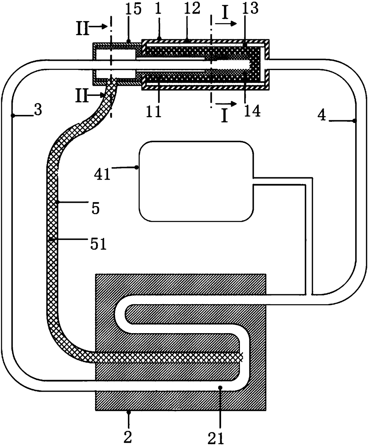
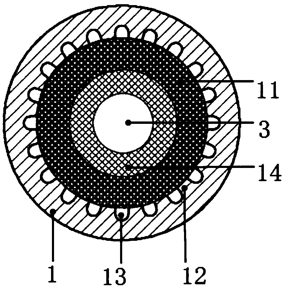
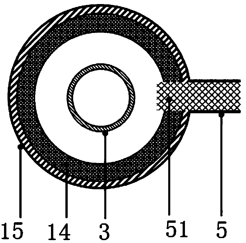
[0024] see Figure 1-Figure 3 , the embodiment of the present invention provides a loop heat pipe with an auxiliary infusion line 5, including an evaporator 1 and a condenser 2, the liquid outlet of the condenser 2 communicates with the liquid inlet of the evaporator 1 through a liquid line 3, and The gas outlet of the evaporator 1 communicates with the inlet of the condenser 2 through the gas pipeline 4, that is, the condenser 2, the liquid pipeline 3, the ev...


PUM


Abstract

The invention relates to heat control equipment, in particular to a loop heat pipe with an auxiliary liquid conveying pipeline. The loop heat pipe comprises an evaporator and a condenser; a liquid outlet of the condenser communicates with a liquid inlet of the evaporator through a liquid pipeline; a gas outlet of the evaporator communicates with a gas inlet of the condenser through a gas pipeline;and the condenser, the liquid pipeline, the evaporator and the gas pipeline communicate in sequence to form a loop. The loop heat pipe further comprises the auxiliary liquid conveying pipeline communicating with the evaporator and the condenser, a first capillary structure is arranged in the auxiliary liquid conveying pipeline, and a liquid absorbing core is arranged in the evaporator. The loop heat pipe is additionally provided with the auxiliary liquid conveying pipeline, the first capillary structure is arranged in the auxiliary liquid conveying pipeline, liquid work media can be conveyedthrough the capillary action of the first capillary structure, continuous liquid work media supplying can be provided for the evaporator without gravity assistance and additional power dissipation, and the starting reliability and the anti-gravity working stability of the loop heat pipe are ensured.

Description

technical field [0001] The invention relates to heat control equipment, in particular to a loop heat pipe with an auxiliary infusion pipeline. Background technique [0002] The loop heat pipe is a thermal control device that utilizes the gas-liquid phase change of the working medium for efficient heat transfer. Compared with the traditional heat pipe, its capillary structure only exists inside the evaporator, and the evaporator and condenser are connected by a thin flexible metal wall. Tube connection, the working fluid flows through metal thin-walled tubes to obtain less flow resistance, and better flexible connection between the cold source and the heat source, to achieve long-distance heat transfer, isolation of vibration and electromagnetic interference, etc., in aerospace , superconductivity, electronic devices and other fields have been widely used. [0003] The start-up process of the existing loop heat pipe before operation is greatly affected by the position status...

Claims


Application Information

Patent Timeline
Patent Type & Authority Applications(China)
IPC IPC(8): F28D15/04
CPCF28D15/0266F28D15/046
Inventor 赵雅楠梁惊涛陈厚磊
Owner TECHNICAL INST OF PHYSICS & CHEMISTRY - CHINESE ACAD OF SCI
Learn More