
Low-frequency electromagnetic vibration table system based on induction coil feedback control

An induction coil and electromagnetic vibration technology, applied in the field of low-frequency electromagnetic vibrating table systems, can solve problems such as unsuitable for vibrating tables, reduce motion accuracy, and affect control effects, so as to reduce the difficulty of construction and parameter adjustment, and improve the effect of negative feedback control , The effect of simplifying the speed detection device

Pending Publication Date: 2018-07-06
ZHEJIANG UNIV
View PDF1 Cites 2 Cited by
  • Summary
  • Abstract
  • Description
  • Claims
  • Application Information

AI Technical Summary

Problems solved by technology

[0005] 1. Since the equivalent DC resistance R of the driving coil of the vibrating table cannot be accurately measured, the parameter K in the relative speed extraction device 1 2. The device extracts the motion of the vibrating table by constructing an analog circuit network. Since a resistor needs to be connected in series in the drive circuit, the heat loss is relatively large, so it is not suitable for Vibration table with high acceleration output
In addition, the system is more complex, and the low-frequency noise of the analog circuit will cause low-frequency drift of the vibrating table during motion, which reduces the motion accuracy
3. The output signal of the relative speed extraction device depends on the parameters of the driving coil. Since the number of turns of the driving coil is limited, the output voltage reflecting the relative speed is low, especially in the lower frequency band, which affects the control effect

Method used


Image

  • Low-frequency electromagnetic vibration table system based on induction coil feedback control
  • Low-frequency electromagnetic vibration table system based on induction coil feedback control
  • Low-frequency electromagnetic vibration table system based on induction coil feedback control

Examples


Embodiment Construction

[0041] The present invention will be further described below in conjunction with specific examples, but the present invention is not limited to these specific embodiments. Those skilled in the art should realize that the present invention covers all alternatives, improvements and equivalents that may be included within the scope of the claims.

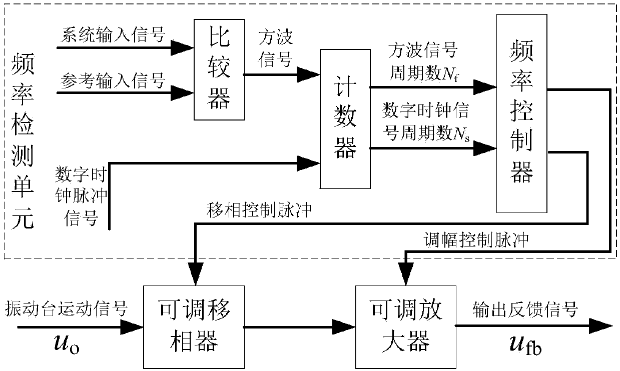
[0042] See figure 1 , figure 2 In Example 1, a low-frequency electromagnetic vibration table system based on induction coil feedback control. The low-frequency electromagnetic vibration table system includes a signal generator, a speed feedback control device, a power amplifier and a low-frequency electromagnetic vibration table; the moving coil of the low-frequency vibration table has Drive coil and induction coil.

[0043] The driving coil and the induction coil are wound together in the same winding slot of the moving part 1 of the vibrating table, or the induction coil and the driving coil are wound side by side in different winding sl...


PUM


Abstract

The invention discloses a low-frequency electromagnetic vibration table system based on induction coil feedback control, which comprises a signal generator, a speed feedback control device, a power amplifier and a low-frequency electromagnetic vibration table. A driving coil and an induction coil are arranged on the moving ring of the low-frequency vibration table. The speed feedback control device comprises a feedback part and a control part. the induced voltage input feedback part of the induction coil, the reference signal output by the signal generator and the feedback signal output by thefeedback part are respectively input to the control part, and the control section forms a control signal input drive coil with a reference signal and a feedback signal. According to the invention, aninduction coil is arranged on the vibrating table moving ring, the vibration table speed extraction is realized by detecting the induction voltage of the induction coil, the equivalent resistance ofthe driving coil is not directly detected, and the speed detection network constructed by the method does not need series resistance on the driving coil and establishes a corresponding analog circuit,so that the structure of the speed extraction device is simplified.

Description

Technical field [0001] The invention relates to a low-frequency electromagnetic vibration table system. Background technique [0002] Electromagnetic vibration table has the advantages of wide frequency range, good controllability, and high output waveform accuracy. It is widely used in product simulation vibration environment test, vibration sensor calibration and other fields. In order to further improve the accuracy of the output waveform of the vibration table in the low frequency range (to reduce distortion), it is usually necessary to construct a negative feedback control system. Negative feedback control first needs to detect the output vibration signal of the electromagnetic vibrating table through a vibration sensor (acceleration, speed or displacement sensor) or other motion detection device, and then use this signal as a feedback signal to calculate the difference with the input signal, and the deviation signal is passed through the controller Excite the vibration of ...

Claims


Application Information

Patent Timeline
IPC IPC(8): G01M7/02
CPCG01M7/022
Inventor 何闻高宇张旭飞贾叔仕
Owner ZHEJIANG UNIV
Learn More