Measuring system and method of short wave antenna directional diagram and gain

A short-wave antenna and pattern technology, applied in the antenna radiation pattern and other directions, can solve the problems of low measurement accuracy of the pattern, inability to obtain the pattern in real time, and inability to measure the gain of the short-wave antenna, so as to achieve real-time drawing and avoid low measurement accuracy , the effect of improving the accuracy

Pending Publication Date: 2018-07-06
XIAN XINGWANG ANTENNA TECH
View PDF1 Cites 15 Cited by
  • Summary
  • Abstract
  • Description
  • Claims
  • Application Information

AI Technical Summary

Problems solved by technology

Although this invention provides a method for measuring the three-dimensional pattern of the short-wave receiving antenna, the defect is that the measurement accuracy of

Method used


Image

  • Measuring system and method of short wave antenna directional diagram and gain
  • Measuring system and method of short wave antenna directional diagram and gain
  • Measuring system and method of short wave antenna directional diagram and gain

Examples


Embodiment Construction

[0037] The present invention will be further described in detail below in conjunction with the accompanying drawings and specific embodiments.

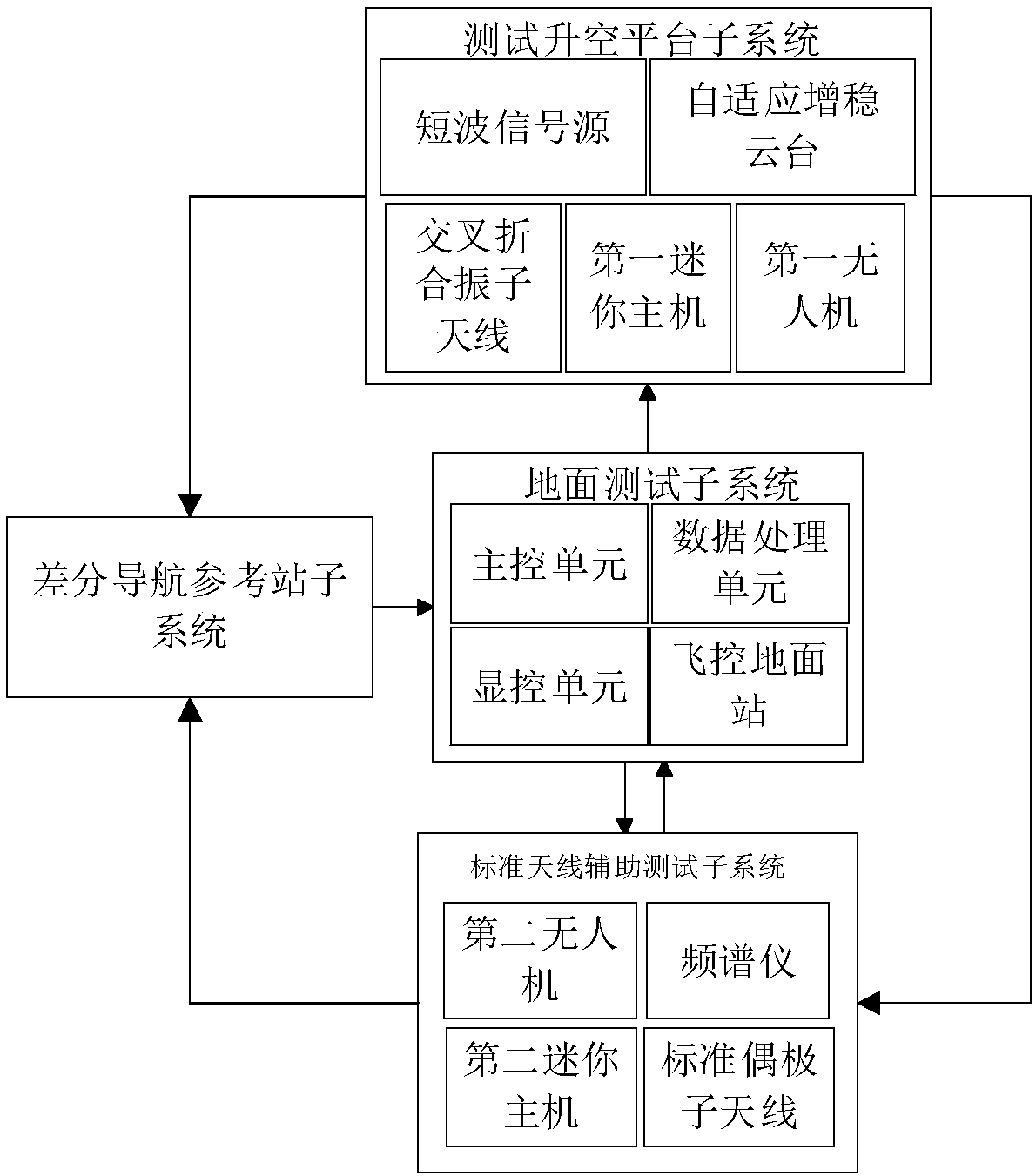
[0038] refer to figure 1 , a measurement system for short-wave antenna pattern and gain, including a ground test subsystem, a test lift-off platform subsystem, a standard antenna auxiliary test subsystem and a differential navigation reference station subsystem, wherein:

[0039] The ground test subsystem includes a main control unit, a data processing unit, a display control unit and a flight control ground station, among which: the main control unit is used to send instructions to the mini-host of the test lift-off platform subsystem to realize real-time measurement of the measurement process Control, and send instructions to the mini-host of the test lift-off platform subsystem and the standard antenna auxiliary test subsystem to realize real-time control of the calibration process, and at the same time receive the measurement data...


PUM


Abstract

The invention provides a measuring system and method of a short wave antenna directional diagram and a gain, and aims at improving the measuring precision of the short wave antenna directional diagram, measuring the gain of short wave antennas and displaying the short wave antenna directional diagram in real time. The implementation method comprises the steps of determining frequency points of thedirectional diagram and the gain which need to be measured; selecting antennas for a second drone of a standard antenna assisting testing subsystem; using a ground testing subsystem to control the standard antenna assisting testing subsystem and a testing liftoff platform subsystem to calibrate level values on working frequency points of to-be-tested short-wave antennas, and using a differentialnavigation reference station subsystem to correct the relative position of the drone; using the ground testing subsystem to control the testing liftoff platform subsystem to measure level value data on the working frequency points of the to-be-tested short-wave antennas, using the differential navigation reference station subsystem to correct a navigation track of a first drone, and using the ground testing subsystem to display measurement data in real time and draw the directional diagram; using the ground testing subsystem to calculate the gain values of the to-be-tested short-wave antennas.

Description

technical field [0001] The invention belongs to the technical field of antenna measurement, and relates to a system and method for measuring the pattern and gain of a short-wave antenna, which can be used to obtain the gain and pattern of the short-wave antenna. Background technique [0002] Short-wave communication still plays an important role in the communication field of various countries. Short-wave antenna is the core equipment in short-wave communication. The performance of the antenna will directly affect the actual communication effect. In order to accurately measure the pattern and gain of the antenna, the measurement of the conventional antenna is carried out in the microwave anechoic room. However, due to the large size of the short-wave antenna and the extremely long distance of the far field of the antenna, the microwave anechoic room does not have enough space for measurement. At present, people mainly obtain the pattern and gain of the short-wave antenna thro...

Claims


Application Information

Patent Timeline
IPC IPC(8): G01R29/10
CPCG01R29/10
Inventor 毛子强何帅张辉方涛岳正鹏鲍重兴杨康敏钟志浩
Owner XIAN XINGWANG ANTENNA TECH
Why Eureka
Try Eureka