Automatic aperture adjusting structure and adjusting method

A technology of automatic adjustment and aperture, applied in aperture, optics, camera and other directions, can solve the problems of high motor cost and high requirements for motor use environment, and achieve the effect of low cost, simple structure and high precision

Pending Publication Date: 2018-07-06
深圳市星河泉新材料有限公司
View PDF1 Cites 13 Cited by
  • Summary
  • Abstract
  • Description
  • Claims
  • Application Information

AI Technical Summary

Problems solved by technology

[0003] The traditional device for adjusting the size of the aperture mainly includes a drive device and an adjustment device, and the drive device is generally a motor drive device. For example, the Chinese patent authorization announcement number CN207008256U discloses an automatic aperture adjustment device, but the motor cost of this patent is high, and the motor It has high requirements for the use environment and is not suitable for outdoor or open-air environments, so as to avoid performance problems caused by water ingress or other environmental factors of the motor

Method used


Image

  • Automatic aperture adjusting structure and adjusting method
  • Automatic aperture adjusting structure and adjusting method
  • Automatic aperture adjusting structure and adjusting method

Examples


Embodiment 1

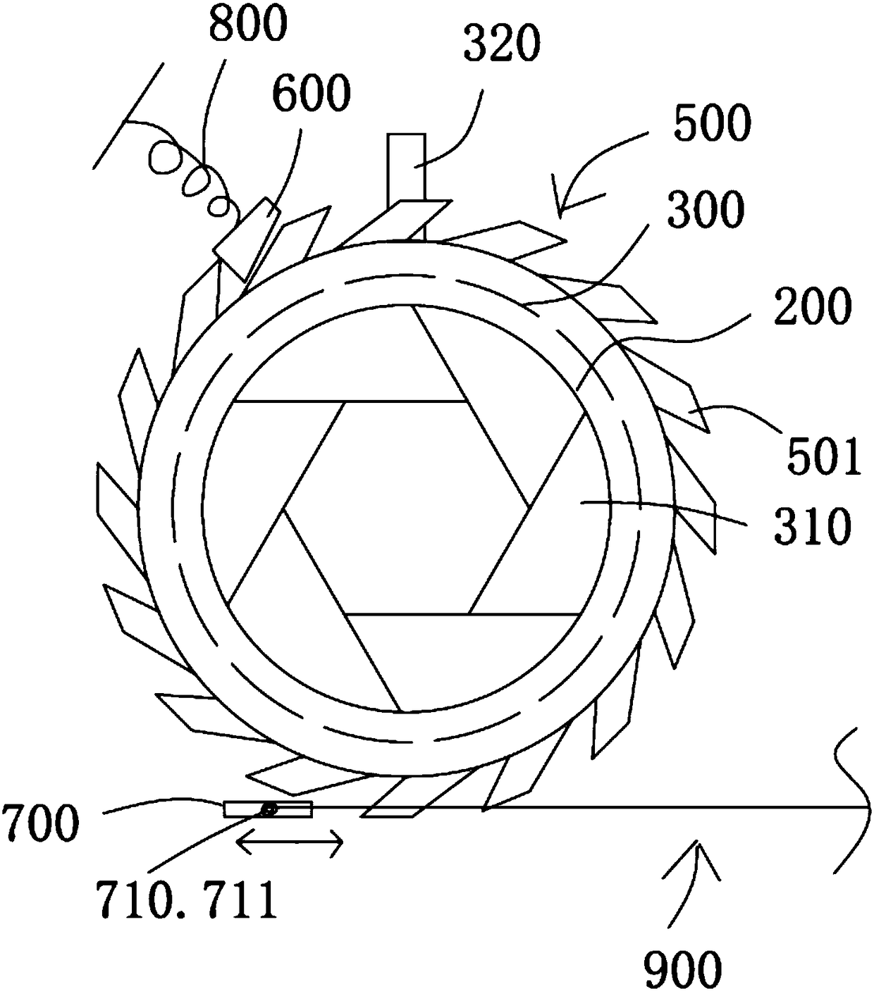
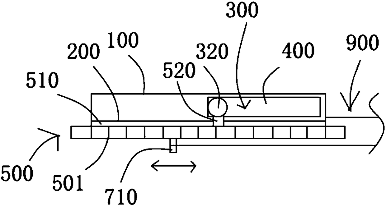
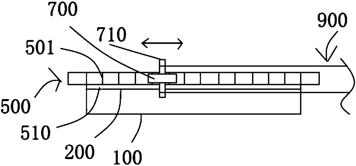
[0031] see Figure 1 to Figure 3 An automatic aperture adjustment structure is shown, including an aperture base plate 100, an aperture back plate 200 used in conjunction with the aperture base plate 100, and an aperture paddle 300 arranged between the aperture base plate 100 and the aperture back plate 200 and installed on the aperture base plate 100 . The aperture paddle 300 is provided with a plurality of blades 310 , the aperture paddle 300 has a driving part 320 connected to the driving assembly, and the aperture bottom plate 100 or the aperture backboard 200 is provided with a limiting portion 400 to limit the movable stroke of the driving portion 320 . The limiting part 400 in this embodiment is an arc-shaped groove with a central angle of 90°, the driving part 320 is a driving rod, and the positions of the two ends of the driving part 320 in the arc-shaped groove are respectively two limit positions. The above-mentioned technology is the same as the aperture principle...

Embodiment 2

[0038] see Figure 4 As shown, the general structure of this embodiment is the same as that of Embodiment 1, the difference is that the teeth 501a of the ratchet ring 500a are helical teeth, the direction of movement of the driving pawl 700a is parallel to the direction of inclination of the helical tooth structure, and the driving pawl 700a One end facing the forward rotation of the ratchet ring 500a is provided with a reset compression part 710a. The second memory alloy element 900a includes a memory alloy wire that drives the movement of the ratchet 700a. The reset compression part 710a includes a compression spring 711a and a compression spring connected with the compression spring. Tight ball 712a.

[0039]The principle of braking and gear adjustment of the ratchet ring 500a in this embodiment is the same as that of Embodiment 1, the difference lies in the way that the driving pawl 700a cooperates with the second memory alloy element 900a to drive the ratchet ring 500a to...


PUM


Abstract

The invention discloses an automatic aperture adjusting structure, which comprises an aperture bottom plate, an aperture back plate matched with the aperture bottom plate, and an aperture dial piece arranged between the aperture bottom plate and the aperture back plate and installed on the aperture bottom plate; multiple blades are arranged on the aperture dial piece, and the aperture dial piece is provided with a driving part connected with the driving component; a limiting part for limiting the activity route of the driving part is arranged on the aperture bottom plate or the aperture back plate; the driving component comprises a ratchet ring rotationally arranged on the aperture back plate and a brake ratchet pawl and a driving ratchet pawl; the ratchet ring is provided with a connecting part connected with the driving part; a reset elastic component is further arranged between the ratchet ring and the aperture back plate; the brake ratchet pawl limits the unidirectional rotation ofthe ratchet wheel ring and connected with a first memory alloy element; the driving ratchet pawl is matched with a tooth of the ratchet ring and connected with a second memory alloy element.

Description

technical field [0001] The invention relates to an aperture adjustment device, in particular to an automatic aperture adjustment structure and adjustment method. Background technique [0002] The aperture is a device used to control the amount of light passing through the lens to the photosensitive surface inside the camera body, which is usually inside the lens. For the manufactured lens, it is impossible for us to change the diameter of the lens at will, but we can control the amount of light passing through the lens by adding a polygonal or circular grating with a variable area inside the lens. This device is called the aperture. [0003] The traditional device for adjusting the size of the aperture mainly includes a driving device and an adjusting device, and the driving device is generally a motor driving device. For example, the Chinese patent authorization announcement number CN207008256U discloses an automatic aperture adjusting device, but the motor cost of this pat...

Claims


Application Information

Patent Timeline
IPC IPC(8): G03B9/06
CPCG03B9/06
Inventor 王思泉
Owner 深圳市星河泉新材料有限公司
Why Eureka
Try Eureka