Beam monitoring object determination method and device
A determination method and beam technology, applied in the field of virtual reality, can solve problems such as the difficulty of beam monitoring, and achieve the effect of improving reliability
- Summary
- Abstract
- Description
- Claims
- Application Information
AI Technical Summary
Problems solved by technology
Method used
Image

Examples
Embodiment 1
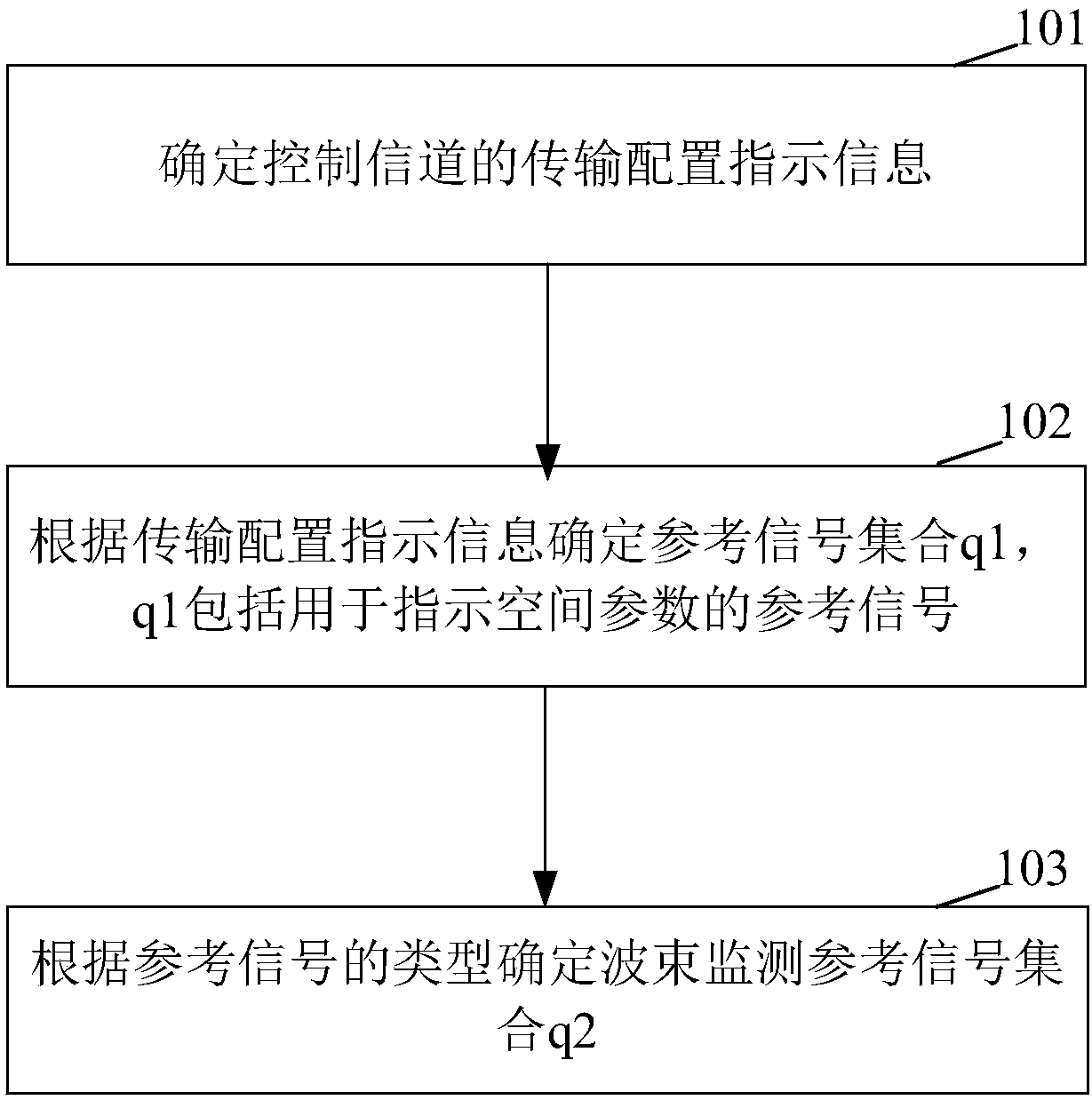
[0086] Such as figure 1 As shown, the embodiment of the present disclosure provides a method for determining a beam monitoring object, including:
[0087] Step 101: Determine TCI (Transmission Configuration Indication) information of the control channel;
[0088] Generally speaking, TCI information is configured through high-level signaling or Media Access Control (MAC, Media Access Control) signaling. TCI is mainly used to indicate transmission-related parameters, such as quasi-co-location QCL parameters.
[0089] Step 102: Determine a reference signal set q1 according to the transmission configuration indication information, where q1 includes reference signals for indicating spatial parameters;
[0090] It should be noted that QCL parameters include QCL indications about spatial parameters. The spatial parameters generally represent the transmission beam implicitly, which indicates a reference signal or a group of reference signals that are relatively close to the spatial parameters ...
Embodiment 2
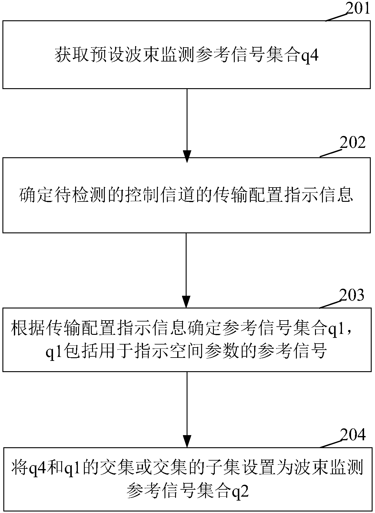
[0098] Such as figure 2 As shown, the embodiment of the present disclosure provides a method for determining a beam monitoring object, including:
[0099] Step 201: Obtain a preset beam monitoring reference signal set q4;
[0100] Step 202: Determine the transmission configuration indication information of the control channel to be detected;
[0101] Step 203: Determine a reference signal set q1 according to the transmission configuration indication information, where q1 includes reference signals for indicating spatial parameters;
[0102] Step 204: Set the intersection of q4 and q1 or a subset of the intersection as the beam monitoring reference signal set q2.
[0103] It is understandable that since aperiodic reference signals may be excluded, the beam monitoring reference signal set q2 may also be set to a subset of the intersection of q4 and q1.
[0104] Optionally, if there is no intersection between q4 and q1, then q2 is q1, or a subset of q1, or an empty set.
[0105] It is under...
Embodiment 3
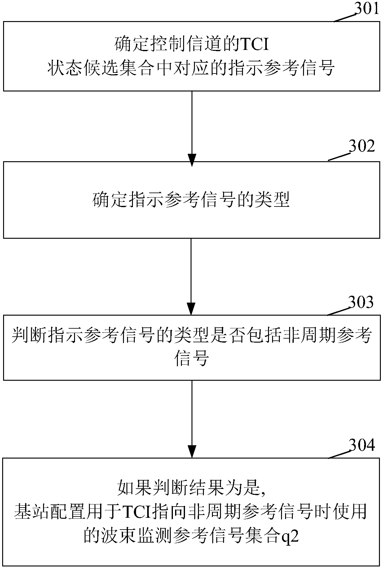
[0109] Such as image 3 As shown, the embodiment of the present disclosure provides a configuration method, including:
[0110] Step 301: Determine the corresponding indication reference signal in the TCI state candidate set of the control channel;
[0111] Wherein, the indication reference signal corresponds to the spatial parameter of the state in the TCI state candidate set.
[0112] Step 302: Determine the type of the indicated reference signal;
[0113] Step 303: Determine whether the type of the indicated reference signal includes an aperiodic reference signal;
[0114] Step 304: If the judgment result is yes, the base station configures the beam monitoring reference signal set q2 used when the TCI points to the aperiodic reference signal.
PUM
 Abstract
Description
Claims
Application Information
 - R&D
- Intellectual Property
- Life Sciences
- Materials
- Tech Scout
- Unparalleled Data Quality
- Higher Quality Content
- 60% Fewer Hallucinations
Browse by: Latest US Patents, China's latest patents, Technical Efficacy Thesaurus, Application Domain, Technology Topic, Popular Technical Reports.
© 2025 PatSnap. All rights reserved.Legal|Privacy policy|Modern Slavery Act Transparency Statement|Sitemap|About US| Contact US: help@patsnap.com