Control device for hybrid power

A control device and hybrid technology, applied in power plants, hybrid vehicles, pneumatic power plants, etc., can solve the problems of high transmission cost, limited motor power, impact, etc., and achieve smooth and comfortable acceleration and deceleration without power. Loss and impact effects

Pending Publication Date: 2018-07-10
XIAMEN FUGONG POWER TECH
View PDF10 Cites 3 Cited by
  • Summary
  • Abstract
  • Description
  • Claims
  • Application Information

AI Technical Summary

Problems solved by technology

[0002] At present, the current control systems of hybrid electric buses mainly include direct drive system, AMT system and single planetary row system. Since the direct drive system does not have a gearbox, it mainly optimizes the working efficiency of the motor and the load rate of the engine. Under low-speed and high-speed conditions, the engine speed cannot be operated in the high-efficiency zone, which cannot be changed by strategy optimization
The AMT system can realize the engine and motor to always work in the high-efficiency zone by designing a reasonable speed ratio. To adapt to all working conditions, more gears are needed to adjust the speed, which leads to the high cost of the gearbox and is unavoidable. There are problems of power interruption and shock during the shifting process
The single planetary row system can realize infinitely variable speed, no power interruption and no shifting shock, but because the power of the motor is limited, it cannot meet the needs of the engine in the high-efficiency zone under all working conditions.

Method used


Image

  • Control device for hybrid power
  • Control device for hybrid power
  • Control device for hybrid power

Examples


Embodiment 1

[0030] Please refer to Figure 1-Figure 6 , Embodiment 1 of the present invention is:

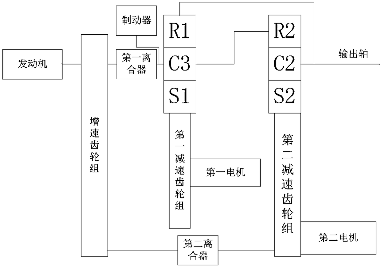
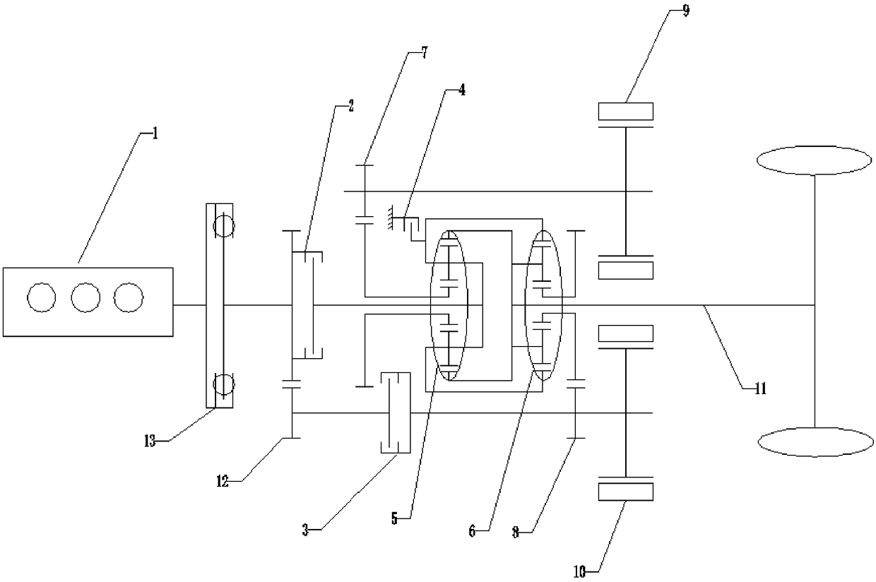
[0031] A hybrid control device, including an engine 1, a first clutch 2, a second clutch 3, a brake 4, a first planetary row 5, a second planetary row 6, a first reduction gear set 7, and a second reduction gear set 8 , the first motor 9, the second motor 10 and the output shaft 11, the engine, the first planetary row and the second planetary row are arranged in sequence, the engine is connected to the first planetary row through the first clutch, and the engine is connected to the first planetary row through the first The second clutch is connected with the second motor;

[0032] The first planetary row includes a first ring gear R1, a first planetary carrier C3 and a first sun gear S1, and the second planetary row includes a second ring gear R2, a second planetary carrier C2 and a second sun gear S2, The first ring gear is coaxially connected to the second planet carrier, the second pla...


PUM


Abstract

The invention provides a control device for hybrid power. A four-shaft transmission system is composed of three input shafts and an output shaft, wherein the three input shafts include a first motor,a second motor and an engine, and a more flexible working adjustment mode is achieved, the first motor and the second motor regulate the speed of the engine, and the control device can adapt to more complicated road conditions. By adjusting the rotating speed of a first gear ring, a first planet carrier, a first sun wheel, a second gear ring, a second planet carrier and a second sun wheel, whereinthe first gear ring, the first planet carrier, the first sun wheel belong to a first planetary row, and the second gear ring, the second planet carrier and the second sun wheel belong to a second planetary row, the whole control device can work like a constantly variable transmission, without the shifting process during the entire driving process, without power loss and impact, the acceleration process and the deceleration process are smooth and comfortable, and an engine and a motor of a hybrid power bus can always work in the high efficiency zone when the hybrid power bus is in different working modes.

Description

technical field [0001] The invention relates to the field of hybrid electric buses, in particular to a hybrid electric control device. Background technique [0002] At present, the current control systems of hybrid electric buses mainly include direct drive system, AMT system and single planetary row system. Since the direct drive system does not have a gearbox, it mainly optimizes the working efficiency of the motor and the load rate of the engine. Under low-speed and high-speed working conditions, the engine speed cannot be made to work in the high-efficiency zone, which cannot be changed by the optimization of the strategy. The AMT system can realize the engine and motor to always work in the high-efficiency zone by designing a reasonable speed ratio. To adapt to all working conditions, more gears are needed to adjust the speed, which leads to the high cost of the gearbox and is unavoidable. There are problems of power interruption and impact during the shifting process....

Claims


Application Information

Patent Timeline
Patent Type & Authority Applications(China)
IPC IPC(8): B60K6/44B60K6/365B60K6/543B60K6/38
CPCB60K6/365B60K6/38B60K6/44B60K6/543B60K2006/381Y02T10/62
Inventor 吕志榕马腾腾兰俊福孟树兴
Owner XIAMEN FUGONG POWER TECH
Why Eureka
Try Eureka