Distributed microsatellite micro-vibration signal acquisition system and application method thereof

A signal acquisition system and micro-satellite technology, which is applied in relay system monitoring, general control system, control/regulation system, etc., can solve the problems that are difficult to meet the requirements of micro-satellite weight reduction, consumption reduction and acquisition accuracy, so as to reduce the difficulty of design , good system scalability and low expansion cost

Active Publication Date: 2021-08-06
NAT UNIV OF DEFENSE TECH
View PDF6 Cites 1 Cited by
  • Summary
  • Abstract
  • Description
  • Claims
  • Application Information

AI Technical Summary

Problems solved by technology

[0004] The technical problem to be solved by the present invention is to provide a distributed micro-satellite micro-vibration signal acquisition system and its application method in view of the fact that the existing micro-vibration signal acquisition system is difficult to meet the requirements of micro-satellites for weight reduction, consumption reduction and acquisition accuracy. Solve the high-precision measurement and reliable downloading of micro-vibration signals under the operation of micro-satellites in orbit, and provide additional temperature measurement functions required by satellite thermal control subsystems

Method used


Image

  • Distributed microsatellite micro-vibration signal acquisition system and application method thereof
  • Distributed microsatellite micro-vibration signal acquisition system and application method thereof
  • Distributed microsatellite micro-vibration signal acquisition system and application method thereof

Examples


Embodiment Construction

[0038] The following will clearly and completely describe the technical solutions in the embodiments of the present invention with reference to the accompanying drawings in the embodiments of the present invention. Obviously, the described embodiments are only part of the embodiments of the present invention, not all of them. Based on the embodiments of the present invention, all other embodiments obtained by persons of ordinary skill in the art without creative efforts fall within the protection scope of the present invention.

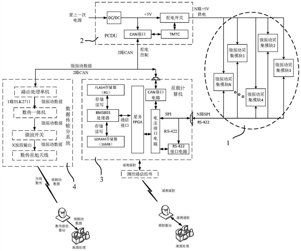
[0039] Such as figure 1 As shown, the distributed micro-satellite micro-vibration signal acquisition system of this embodiment includes a distributed digital micro-vibration acquisition array 1, a power control distribution stand-alone 2, an on-board computer 3 and a data transmission subsystem 4, and a distributed digital micro-vibration acquisition array 1 includes a plurality of micro-vibration acquisition modules respectively installed on differen...


PUM


Abstract

The invention discloses a distributed microsatellite micro-vibration signal acquisition system and an application method thereof, and the system comprises a distributed digital micro-vibration acquisition array, a power supply control distribution single machine, a spaceborne computer, and a data transmission subsystem. The distributed digital micro-vibration acquisition array comprises a plurality of micro-vibration acquisition modules installed on different vibration transmission paths of a satellite, the power supply ends of the micro-vibration acquisition modules are connected with the output end of a power supply control distribution single machine, the output ends of the micro-vibration acquisition modules are connected with a satellite-borne computer, and the input end of the power supply control distribution single machine is connected with a satellite-borne primary power supply, and the spaceborne computer is respectively connected with the control end of the power supply control distribution single machine and the data transmission subsystem through a bus. Aiming at the problem that the existing micro-vibration signal acquisition system is difficult to meet the requirements of weight reduction, consumption reduction and acquisition precision of the microsatellite, the high-precision measurement and reliable downloading of the micro-vibration signal under the in-orbit operation of the microsatellite can be realized, and meanwhile, a temperature measurement function required by a satellite thermal control subsystem is additionally provided.

Description

technical field [0001] The invention belongs to spacecraft signal acquisition and transmission technology, and in particular relates to a distributed micro-satellite micro-vibration signal acquisition system and an application method thereof. Background technique [0002] High-precision earth observation spacecraft can obtain high-quality remote sensing images, which is of great strategic significance for occupying the strategic commanding heights of space and maintaining national space security. The imaging quality of satellites such as "Gaofen-2" and "Jilin-1" launched by our country has reached sub-meter resolution, but there is still a big gap with the international top level. Among them, a very important factor is that the spacecraft structural platform is disturbed by micro-vibration, its attitude stability and pointing accuracy are seriously affected, which in turn reduces the performance of spaceborne sensitive loads (such as imaging quality, etc.). The current rese...

Claims


Application Information

Patent Timeline
Patent Type & Authority Applications(China)
IPC IPC(8): H04B17/40G01H17/00G05B19/042
CPCH04B17/40G01H17/00G05B19/042
Inventor 吴军李东旭吴国福罗青袁福王杰涂开武
Owner NAT UNIV OF DEFENSE TECH
Why Eureka
Try Eureka