
Automobile front automobile body frame component

A car body frame and automobile technology, which is applied in the connection between the car body and the frame, vehicle components, upper structure, etc. It can solve the problems of restricted cavity size, unfavorable collision performance of the foot pedal installation area, and affecting the welding cycle.

Pending Publication Date: 2018-07-10
SAIC-GM-WULING AUTOMOBILE CO LTD
View PDF9 Cites 0 Cited by
  • Summary
  • Abstract
  • Description
  • Claims
  • Application Information

AI Technical Summary

Problems solved by technology

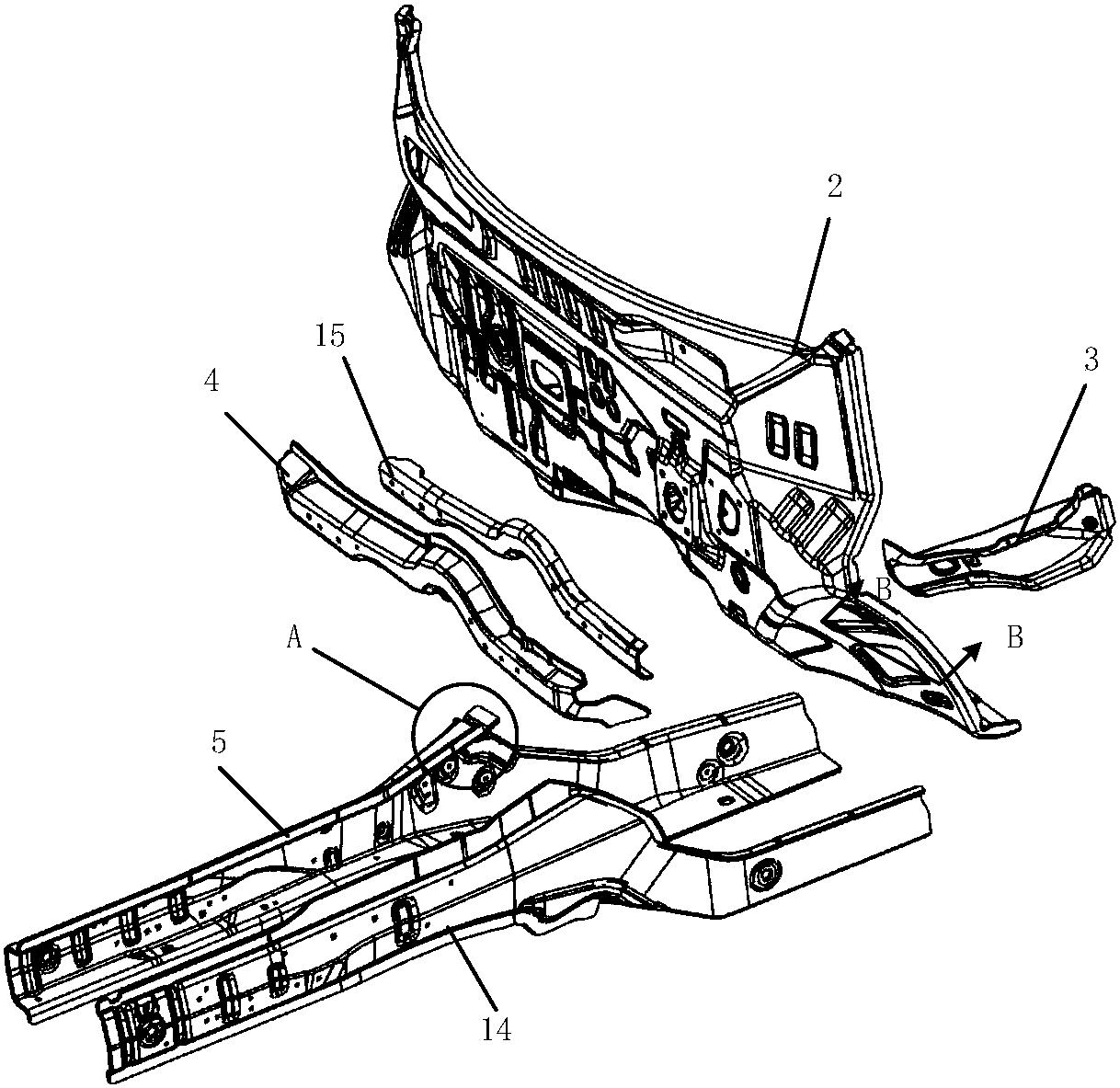
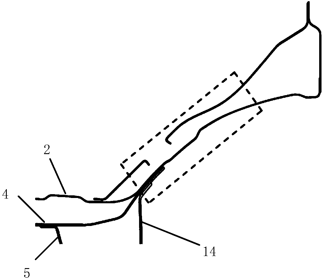
The existing front body assembly has the following disadvantages: the thickness of the dash panel 2 is thin, resulting in a relatively weak rigidity in the area of ​​the wheel housing of the dash panel 2, and the size of the cavity is limited by the envelope layout space of the pedals and tires, which is not conducive to improving the installation of the pedals. Regional crash performance
It is difficult to match the front beam 4 and the front beam 5
The assembly welding process of the front beam 4 and the front frame 5 is relatively complicated
The disadvantage of another structure is that the structure is relatively complicated
There are many parts, the precision of sub-assembly and welding is high, and the mold cost is relatively high
Multi-board overlapping, more glue coating, relatively high cost, and at the same time affect the welding beat
It is difficult to seal the overlapping joints of multiple plates

Method used


Image

  • Automobile front automobile body frame component
  • Automobile front automobile body frame component
  • Automobile front automobile body frame component

Examples


Embodiment Construction

[0039] The following with attached Figure 8 to Figure 17 A car front body frame assembly of the present invention is further described in detail.

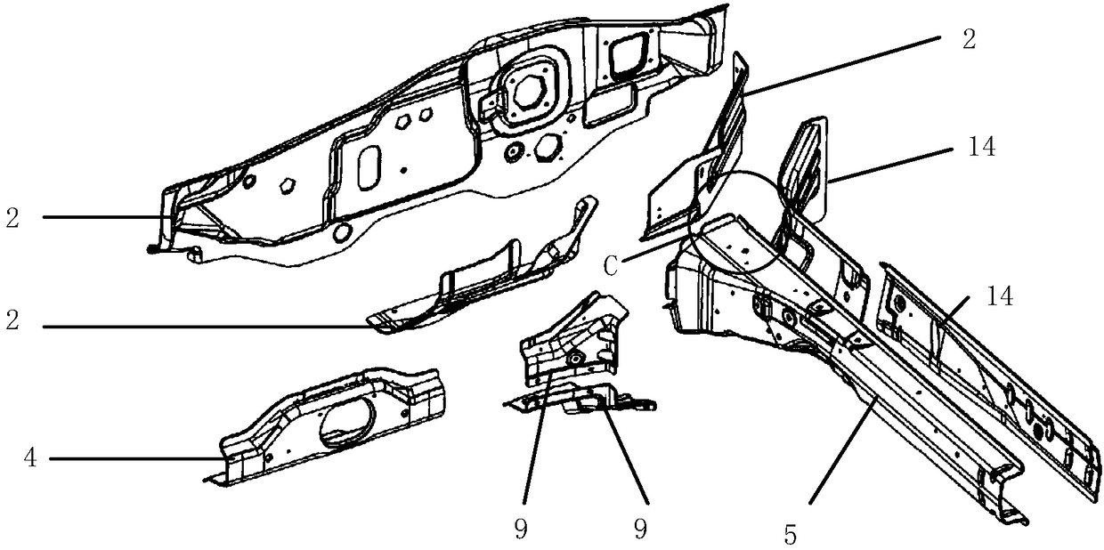
[0040] A kind of automobile front body frame assembly of the present invention, please refer to Figure 8-17, comprising a front anti-collision beam 1, a dash panel 2, a dash panel reinforcing plate 3, a front beam 4 and a front beam 5, the dash panel 2 is fixed on the rear portion of the front cross beam 4, and the dash panel reinforces The panel 3 is located at the rear of both ends of the dash panel 2, the dash panel reinforcement plate 3 is fixedly connected with the dash panel 2 to form a dash panel cavity 6, and the left and right ends of the front beam 4 are connected to the dash panel The left and right ends of the dash panel 2 are fixedly connected to form a closed cross beam cavity 7, the cross beam cavity 7 corresponds to the front and rear positions of the dash panel cavity 6, and the rear end of the front frame 5 is ...


PUM

PropertyMeasurementUnit
Thicknessaaaaaaaaaa
Thicknessaaaaaaaaaa

Abstract

The invention discloses an automobile front automobile body frame component which comprises a front anti-collision beam, a front wall plate, front wall plate reinforcing plates, a front crossbeam andfront girders. The front wall plate is fixed to the rear portion of the front crossbeam, the front wall plate reinforcing plates are located on the rear portions at the two ends of the front wall plate and fixedly connected with the front wall plate to form front wall plate cavities, the left end and the right end of the front crossbeam are fixedly connected with the left end and the right end ofthe front wall plate to form closed crossbeam cavities, the front and back positions of the crossbeam cavities and the front wall plate cavities correspond to each other, the rear ends of the front girders are longitudinally fixed to the front portions of the left end and the right end of the front crossbeam, and the front anti-collision beam is fixed between the front ends of the front girders onthe left side and the right side. By the adoption of the provided automobile front automobile body frame component, the matching accuracy of the front crossbeam and the front girders, the material use rate, the stamping forming quality and the collision performance of a front automobile body can be improved, the intrusion amount of installation regions of the front wall plate and pedals is reduced, and the manufacturing difficulty and the part cost are reduced.

Description

technical field [0001] The invention relates to the technical field of automobile front body, in particular to an automobile front body frame assembly. Background technique [0002] At present, on the front body of a traditional passenger car, the frame structure is usually formed by arranging the front frame 5 on both sides, and setting the front anti-collision beam 1 and the front cross member 4 between the front frame 5, and then the front cross member 4 The dash panel 2 is arranged on the vehicle frame at the rear, so that the front girder 5, the front cross member 4 and the dash panel 2 are connected by a welding process, so that the front body forms a frame-type cavity structure to enhance the stability of the front body. Crash performance and load carrying capacity. [0003] Figure 1-8 It is a schematic diagram of the joint structure of the common front frame and dash panel. The existing front body assembly has the following disadvantages: the thickness of the dash...

Claims


Application Information

Patent Timeline
IPC IPC(8): B62D24/00B62D21/15B62D25/08
CPCB62D21/152B62D24/00B62D25/08
Inventor 劳兵周士智刘亚刘烨陈聪
Owner SAIC-GM-WULING AUTOMOBILE CO LTD
Learn More