
A bladeless fan powered vertical take-off and landing UAV

A bladeless fan and drone technology, applied in the field of drones, can solve the problems of poor safety, complex structure, high manufacturing cost, etc.

Inactive Publication Date: 2019-05-10
曹蔚萌
View PDF7 Cites 0 Cited by
  • Summary
  • Abstract
  • Description
  • Claims
  • Application Information

AI Technical Summary

Problems solved by technology

[0004] In order to solve the problem that the existing UAV uses the interaction between the rotation of the blade and the air to generate lift, the number of components required to realize the above process is large, the structure is complex, the manufacturing cost is high, the maintenance cost is expensive, the maintenance workload is large, and the safety is poor , the present invention provides a bladeless fan powered vertical take-off and landing unmanned aerial vehicle, the technical solution adopted is:

Method used


Image

  • A bladeless fan powered vertical take-off and landing UAV
  • A bladeless fan powered vertical take-off and landing UAV
  • A bladeless fan powered vertical take-off and landing UAV

Examples


Embodiment approach 1

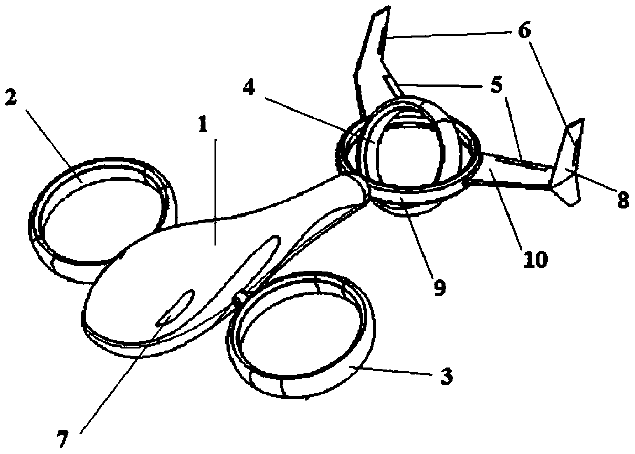
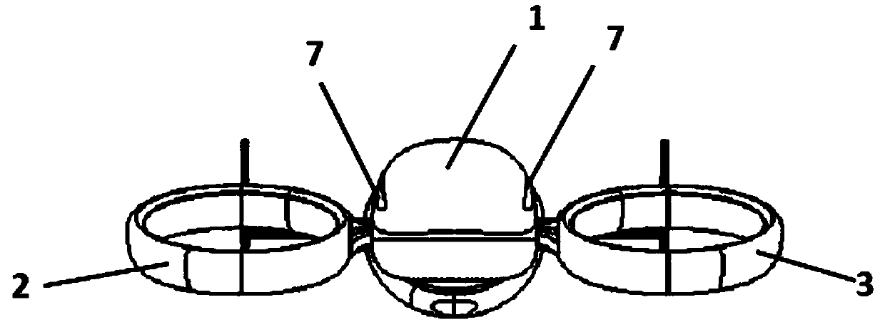
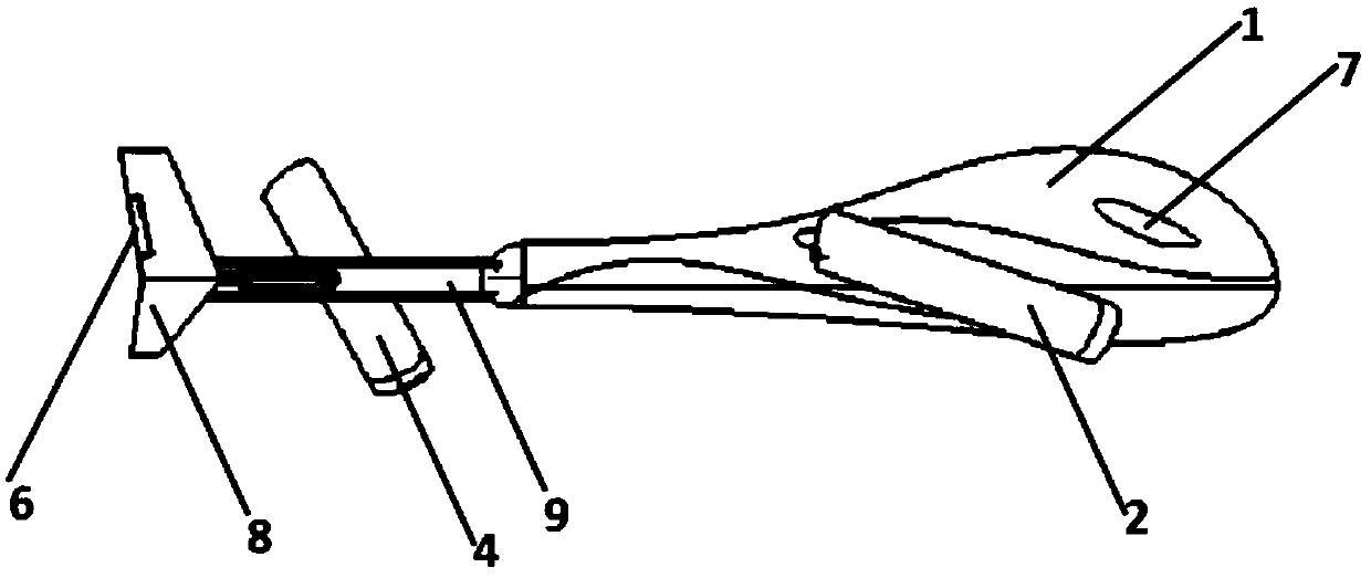
[0033] combine Figure 1-4Describe this embodiment, a bladeless fan power vertical take-off and landing UAV in this embodiment, the UAV includes a streamlined body 1, a bladeless power fan I2, a bladeless power fan II3, a bladeless power fan III4, pitch control surface 5, yaw control surface 6, horizontal empennage 10, vertical empennage 8, turbocharged jet engine, hollow fixed ring 9 and battery; Wherein: described bladeless power fan I2 and bladeless power The fan II3 is symmetrically fixed and installed on both sides of the streamlined body 1 through hollow fixed connectors. The plane of the annular wind circle of the bladeless power fan I2 and the plane of the annular wind circle of the bladeless power fan II3 and the horizontal plane are 0 °~30°; the fixed ring 9 is fixedly installed on the tail of the streamlined body 1, and the fixed ring 9 is arranged along the horizontal direction; the outer ring surface of the fixed ring 9 is fixed with two horizontal tail fins 10, a...

Embodiment approach 2

[0042] This embodiment further limits the pitch control surface 5 in the first embodiment. In this embodiment, the pitch control surface 5 can adjust the angle formed by the pitch control surface 5 and the horizontal stabilizer through the steering gear.

Embodiment approach 3

[0044] This embodiment is further limited to the pitch control surface 5 in the first or second embodiment. In this embodiment, the adjustment range of the angle formed by the pitch control surface 5 and the horizontal stabilizer surface is -30°-30°.

[0045] In this embodiment, when the angle between the pitch control surface 5 and the horizontal stabilizer surface is 0°, it is the neutral position or the zero position, and the upward deviation is positive, and the downward deviation is negative.


PUM


Abstract

The invention discloses a bladeless fan powered vertical take-off and landing unmanned aerial vehicle, which belongs to the technical field of unmanned aerial vehicles. The UAV of the present invention comprises a streamlined body, a bladeless power fan I, a bladeless power fan II, a bladeless power fan III, a pitch control surface, a yaw control surface, a horizontal empennage, a vertical empennage, and a turbocharged jet engine , hollow retaining ring and battery. The drone of the present invention uses the principle of a bladeless fan to generate the lift required for flight, and cancels the entire rotor system while flying normally, thereby avoiding a series of maintenance and cost pressures brought by the use of propeller hub components. The invention has the characteristics of vertical take-off and landing, hovering and high-speed cruising, aims at the new form of war conditions in the future, and can perform surveillance, reconnaissance and electronic warfare tasks.

Description

technical field [0001] The invention relates to a bladeless fan powered vertical take-off and landing unmanned aerial vehicle, which belongs to the technical field of unmanned aerial vehicles. Background technique [0002] The main components of traditional unmanned helicopters that generate lift are generated by the interaction between the rotation of the blades in the rotor system and the air. The blades are connected to the main shaft of the rotor by the hub, and the hub is a key component that is constantly changing. Type technology is the core technology of the helicopter. In the early articulated propeller hubs, there were not only swinging hinges, shimmy hinges and pitch-changing hinges, but also various bearings, shimmy reducers, stoppers, etc. The structure was complex and the number of parts was large, not only the manufacturing cost was high, The maintenance cost is expensive, the maintenance workload is heavy, and the security is poor. [0003] First introduced...

Claims


Application Information

Patent Timeline
Patent Type & Authority Patents(China)
IPC IPC(8): B64C1/06B64C29/00B64D27/16
CPCB64C1/068B64C29/00B64D27/16B64U10/00B64U50/12
Inventor 曹蔚萌
Owner 曹蔚萌
Learn More