Prefabricated laminated anti-collision wall for urban viaduct and construction method thereof

A technology of anti-collision walls and viaducts, which is applied in the direction of erecting/assembling bridges, bridges, and bridge parts, etc., which can solve the problems of poor quality of pouring, low construction efficiency, and long construction period, so as to improve quality and construction efficiency and reduce on-site reinforcement operation and shorten the construction period

Pending Publication Date: 2018-07-10
高强
View PDF0 Cites 5 Cited by
  • Summary
  • Abstract
  • Description
  • Claims
  • Application Information

AI Technical Summary

Problems solved by technology

However, traditional anti-collision walls on both sides of viaducts generally adopt the cast-in-place construction method, which requires complex processes such as steel bar binding, installation of pipeline embedded parts, formwork on both sides of the support, pouring concrete, maintenance, and formwork removal. The construction efficiency is low and the construction period is long. Causes continuous traffic congestion and restricts local economic and social development; and the anti-collision wall is narrow and wide, the quality of on-site pouring is not easy to guarantee, and the phenomenon of honeycomb pockmarks on the concrete surface often occurs, which seriously affects the aesthetics of the anti-collision wall and the durability of the later period It requires frequent maintenance and renovation, resulting in a large waste of human and financial resources; in addition, during on-site construction, workers need to install and dismantle the formwork at high altitude, which is easy to fall and cause safety accidents, and there is a great potential safety hazard

Method used


Image

  • Prefabricated laminated anti-collision wall for urban viaduct and construction method thereof
  • Prefabricated laminated anti-collision wall for urban viaduct and construction method thereof
  • Prefabricated laminated anti-collision wall for urban viaduct and construction method thereof

Examples


Embodiment 1

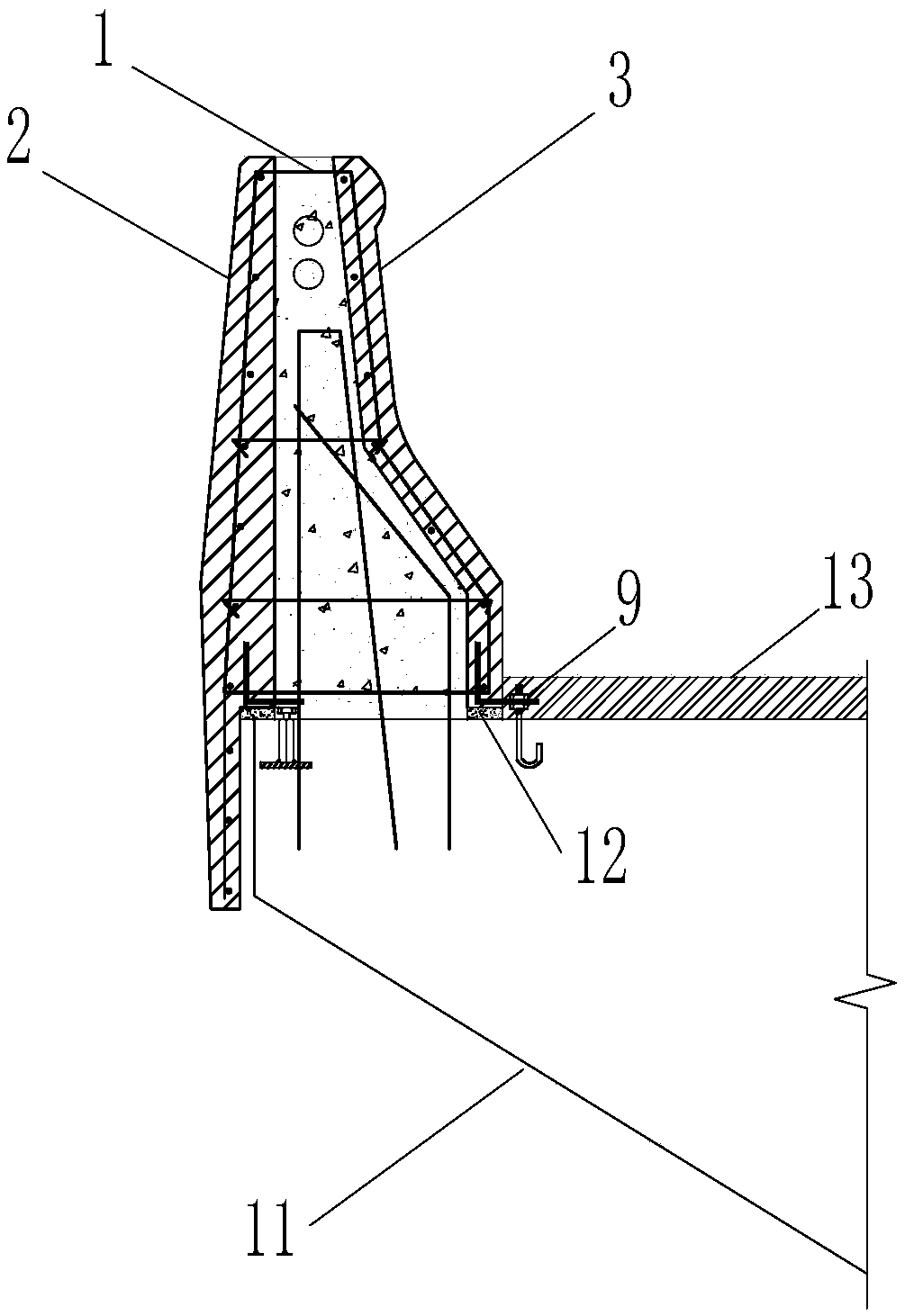
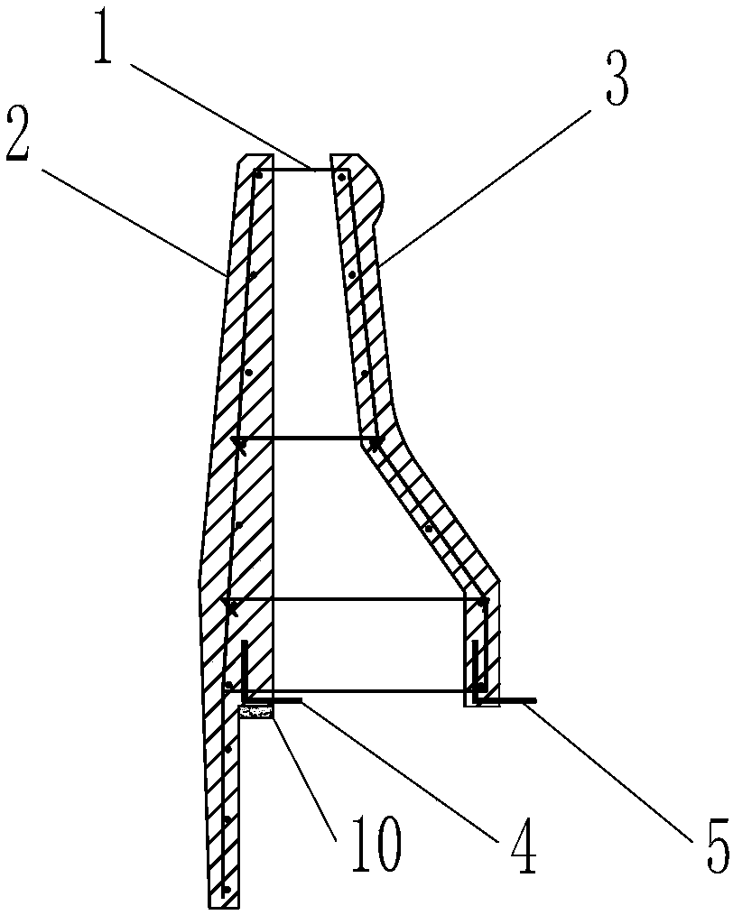
[0032] Such as Figure 1 ~ Figure 4 As shown, the prefabricated laminated anti-collision wall for urban viaducts of the present invention is composed of a cage-shaped steel skeleton 1 connected to an outer precast concrete wall panel 2 and an inner precast concrete wall panel 3, and a cavity is formed in the middle.

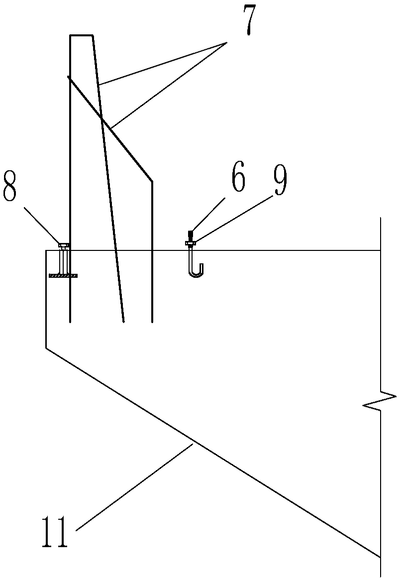
[0033] The intersections of the horizontal bars and the vertical bars of the cage-like reinforcement frame 1 can be welded firmly by spot welding to make the reinforcement cage more stable. It is not only the structural stress reinforcement of the anti-collision wall, but also plays the role of connecting the precast concrete wall panels on both sides of the inside and outside. At the same time, it should also meet the integrity requirements of the components during demoulding, turning, transportation and hoisting. At the construction site, the vertical connecting steel bar 7 is reserved on the surface of the bridge deck 11, and the prefabricated composite anti-c...

Embodiment 2

[0044] Such as Figure 5 As shown, the difference from Example 1 is that the lower part of the outer precast concrete wall panel 2 does not have a lower hanging plate, and the anti-collision wall falls on the top of the bridge deck 11 as a whole, and the gap between the bottom of the outer precast concrete wall panel 2 and the bridge deck 11 is also used. Dry hard cement mortar 12 plugging, all the other are with embodiment 1.

Embodiment 3

[0046] Such as Figure 6 As shown, the difference from Example 1 is that the anti-collision wall is located in the middle of the bridge and acts as a separation strip, and the prefabricated concrete wall panels on both sides of the cage-like steel skeleton 1 (outer precast concrete wall panels 2 and inner precast concrete wall panels 3) at the bottom, L-shaped corbels 5 with holes are pre-embedded, vertical screws 6 are pre-embedded on the top of bridge deck 11, and holes corresponding to pre-embedded vertical screws 6 are opened on the bottom plate of L-shaped corbels 5 with holes. A nut 9 is pre-installed to the screw rod 6 top, and the bottom plate of the L-shaped corbel 5 with holes is inserted into the vertical screw rod 6 during hoisting, and falls on the nut 9 pre-installed below. The gap between the bottom of the precast concrete wall panel and the bridge deck 11 is also sealed with dry hard cement mortar 12, the surface layer 13 of the bridge deck 11 covers the expose...


PUM


Abstract

The invention relates to the technical field of bridge structures, in particular to a prefabricated laminated anti-collision wall for an urban viaduct and a construction method thereof. The anti-collision wall is formed by connecting inner and outer prefabricated concrete wall panels through a cage-shaped steel skeleton, and a cavity is formed in the middle. At the construction site, vertical connection steel bars are reserved in the surface of a bridge deck, the prefabricated laminated anti-collision wall is hoisted to a predetermined position from top to bottom, during the hoisting process,the reserved vertical connection steel bars protrude into the cavity of the prefabricated laminated anti-collision wall, to be lapped and connected with vertical ribs of the cage-shaped steel skeleton, and the prefabricated laminated anti-collision wall is integrated with the bridge deck by pouring concrete into the cavity. The prefabricated laminated anti-collision wall is prefabricated in factory, the pouring quality of the inner and outer concrete wall panels is guaranteed, the processes of on-site mould erecting and demoulding are eliminated, and most of the on-site bars operation is reduced. Compared with the traditional cast-in-place construction method, the on-site construction speed is greatly improved, the construction period is shortened, and the appearance quality and the personal safety of workers are more easily guaranteed.

Description

technical field [0001] The invention relates to the technical field of bridge structures, in particular to a prefabricated composite anti-collision wall for urban viaducts and a construction method thereof. Background technique [0002] At present, with the increasing number of urban vehicles, the smoothness of the main traffic roads in the city is extremely important, and the viaduct often plays a role in urban traffic, carrying a lot of traffic pressure, and its cleanliness and beauty are also important for the appearance of a city. reflect. [0003] Therefore, in the construction or expansion of urban viaducts, the construction period and construction quality are often the focus of decision-makers. However, traditional anti-collision walls on both sides of viaducts generally adopt the cast-in-place construction method, which requires complex processes such as steel bar binding, installation of pipeline embedded parts, formwork on both sides of the support, pouring concre...

Claims


Application Information

Patent Timeline
Patent Type & Authority Applications(China)
IPC IPC(8): E01D19/10E01D21/00E01D101/26
CPCE01D19/103E01D21/00E01D2101/26
Inventor 高强张宇博
Owner 高强
Why Eureka
Try Eureka