Staggered magnetofluid sealing structure

A magnetic fluid sealing and magnetic fluid technology, applied in the direction of engine sealing, engine components, mechanical equipment, etc., can solve the problems of difficult to achieve vacuum sealing, insignificant effect, poor magnetic sealing performance, etc., to improve the pressure resistance and sealing performance. performance, expanding the safe working range, increasing the effect of self-healing capabilities

Inactive Publication Date: 2018-07-10
GUANGXI UNIVERSITY OF TECHNOLOGY
View PDF4 Cites 4 Cited by
  • Summary
  • Abstract
  • Description
  • Claims
  • Application Information

AI Technical Summary

Problems solved by technology

[0005] 1. On the outer surface of the rotating shaft, the area where the magnetic fluid is sealed is the optical axis section. Once the magnetic fluid leaks, it will cause a complete leak and the seal will fail
[0006] 2. If a single-stage seal is used, the magnetic supply capacity is weak, the magnetic sealing performance is poor, and it is difficult to meet the requirements of vacuum sealing; if a multi-stage seal is used, the sealing performance can be improved, but the effect is not obvious, and it cannot reach high speed, etc. The needs of the occasion, the scope of application is narrow
Moreover, the use of multi-stage sealing will make the equipment size large and occupy space

Method used


Image

  • Staggered magnetofluid sealing structure

Examples


Embodiment Construction

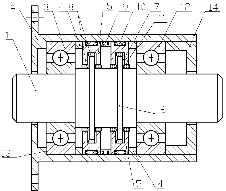
[0025] Such as figure 1 As shown, a staggered magnetic fluid seal structure includes a hollow housing 2, a rotating shaft 1 disposed in the inner cavity of the housing 2, and the rotating shaft 1 and the housing 2 are assembled and connected by bearings.

[0026] A permanent magnet 9 is sleeved on the inner wall of the housing 2 , and pole pieces 5 sleeved on the inner wall of the housing 2 are respectively provided on both sides of the permanent magnet 9 . Each pole shoe 5 is provided with two pole teeth 11 , and a groove 7 is formed between the two pole teeth 11 . The pole piece 5 is a split structure, which is a complete annular pole piece formed by combining two semicircular arc pole pieces.

[0027] Two disk-shaped shafts 6 are arranged in the radial direction of the rotating shaft 1 , and the diameter of the disk-shaped shafts 6 is larger than that of the rotating shaft 1 . The outer edges of each disk-shaped shaft 6 are inserted into the grooves 7 of the pole pieces 5...


PUM


Abstract

The invention discloses a staggered magnetofluid sealing structure. The staggered magnetofluid sealing structure comprises a hollow shell and a rotary shaft, wherein the rotary shaft and the shell areassembled and connected through a bearing; at least one permanent magnet is assembled on the inner wall of the shell; pole shoes mounted on the inner wall of the shell in a sleeving manner are separately arranged on two side of each permanent magnet, at least two polar teeth are arranged on each pole shoe, and a groove is formed between adjacent two polar teeth; at least one disc-shaped shaft isarranged in the radial direction of the rotary shaft, and the diameter of the disc-shaped shaft is greater than that of the rotary shaft; the outer edge of the at least one disc-shaped shaft is correspondingly inserted into the groove of the pole shoe; a gap X exists between the outer edge surface of the disc-shaped shaft and the inner circumferential surface of the groove, and a magnetofluid is injected to the gap X; a gap exists between the polar teeth and the outer circumferential surface of the rotary shaft, and a magnetofluid is injected to the gap Y. By arranging the structure in a staggered manner, the magnetofluid can be blocked well, so that the loss of the magnetofluid is reduced greatly. Meanwhile, the self-repairing ability of the sealing structure is increased, so that the pressure resistance and sealing property of magnetofluid sealing are improved.

Description

technical field [0001] The invention belongs to sealing technology, in particular to a staggered magnetic fluid sealing structure. Background technique [0002] The magnetic fluid seal has the advantages of no solid friction between the seals, long service life of the seals, and zero leakage. [0003] The existing magnetic fluid sealing structure generally includes a housing with a hollow cavity, a rotating shaft, a permanent magnet and a pole shoe are arranged between the rotating shaft and the housing for magnetic fluid sealing, and the inner ring of the pole shoe is provided with pole teeth. [0004] This structure mainly has the following defects: [0005] 1. On the outer surface of the rotating shaft, the area where the magnetic fluid is sealed is the optical axis section. Once the magnetic fluid leaks, it will cause complete leakage and the seal will fail. [0006] 2. If a single-stage seal is used, the magnetic supply capacity is weak, the magnetic sealing performan...

Claims


Application Information

Patent Timeline
Patent Type & Authority Applications(China)
IPC IPC(8): F16J15/43
Inventor 杨小龙陈帆刘纯友何美丽
Owner GUANGXI UNIVERSITY OF TECHNOLOGY
Why Eureka
Try Eureka