Terahertz continuous wave scanning imaging system and method

An imaging method and imaging system technology, applied in the field of terahertz wave imaging, can solve the problems of instrument wear, prolonging the system scanning time, unfavorable instrument protection, etc., and achieve the effect of high degree of automation and flexible expansion.

Active Publication Date: 2018-07-10
SHANDONG ACAD OF SCI INST OF AUTOMATION
View PDF3 Cites 10 Cited by
  • Summary
  • Abstract
  • Description
  • Claims
  • Application Information

AI Technical Summary

Problems solved by technology

The system is highly integrated, but the output terahertz beam bandwidth is narrow, and it is mostly used for point-frequency imaging, and the spectral characteristics of the test sample cannot be obtained
[0004] The transmission of terahertz waves and the reception of echo signals can be realized by using a microwave vector network analyzer and a spread spectrum module, but in the measurement process of S parameters (S11, S21, S12, S22), it is generally necessary to manually set the vector network analyzer various parameters; to realize the imaging algorithm, it is necessary to copy the signal data to the computer for analysis and calculation through a mobile storage device, and the operation efficiency is relatively low
At the same time, repeated manual operations and data copying of the vector network analyzer are likely to cause wear and tear on the instrument, and failure to use the protection of the instrument
[0005] In the existing terahertz continuous wave continuous scanning imaging system using S parameters, at the moment of s

Method used


Image

  • Terahertz continuous wave scanning imaging system and method
  • Terahertz continuous wave scanning imaging system and method
  • Terahertz continuous wave scanning imaging system and method

Examples


Embodiment Construction

[0080] It should be pointed out that the following detailed description is exemplary and intended to provide further explanation to the present application. Unless defined otherwise, all technical and scientific terms used herein have the same meaning as commonly understood by one of ordinary skill in the art to which this application belongs.

[0081] It should be noted that the terminology used here is only for describing specific implementations, and is not intended to limit the exemplary implementations according to the present application. As used herein, unless the context clearly dictates otherwise, the singular is intended to include the plural, and it should also be understood that when the terms "comprising" and / or "comprising" are used in this specification, they mean There are features, steps, operations, means, components and / or combinations thereof.

[0082] As introduced in the background technology, there are many deficiencies in the prior art. In order to sol...


PUM


Abstract

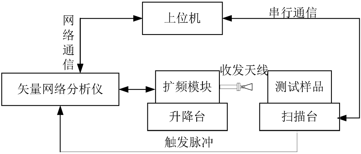
The invention discloses a Terahertz continuous wave scanning imaging system and method. The system comprises a vector network analyzer which is connected to a frequency spread module, a scanning stageand an upper computer separately, and the scanning stage is connected to the upper computer; the frequency spread module is placed on a lifting table, and the lifting table is used for adjusting thehorizontal and vertical position of the frequency spread module away from a test sample; the test sample is fixed to the scanning stage; the upper computer scans parameters, sends a scanning order andcontrols movement of the scanning stage by configuring test samples; the upper computer completes parameter setting of the vector network analyzer, reading of S parameters and test sample scanning imaging display. Accordingly, the upper computer does not need to perform interactive communication with the scanning stage to obtain position coordinates of sampling points, the upper computer obtainsgrayscale images through the methods such as line scanning point number control, data rearrangement and gray value dynamic stretching, the communication link is simplified, the system scanning time isshortened, and the imaging efficiency is improved.

Description

technical field [0001] The invention relates to the technical field of terahertz wave imaging, in particular to a terahertz continuous wave scanning imaging system and method. Background technique [0002] Terahertz Wave (THz for short) usually refers to electromagnetic waves with a frequency between 0.1 and 10 THz (wavelength between 0.03 mm and 3 mm), which can penetrate most non-polar materials, and can penetrate opaque non-polar materials. Imaging of sensitive substances to detect their internal structure and defects. [0003] Most terahertz continuous wave scanning imaging systems use solid-state electronic frequency doubling methods to generate terahertz sources. Integrate optoelectronic devices such as signal sources, phase-locked sources, drivers, frequency multipliers, couplers, mixers, and detectors together to realize the functions of receiving and sending terahertz waves. The system is highly integrated, but the output terahertz beam bandwidth is narrow, and it...

Claims


Application Information

Patent Timeline
IPC IPC(8): G01N23/02G01N21/84
CPCG01N21/84G01N23/02
Inventor 张延波常天英张献生徐文青刘陵玉崔洪亮
Owner SHANDONG ACAD OF SCI INST OF AUTOMATION
Why Eureka
Try Eureka