
High-efficiency hybrid white OLED (Organic Light Emitting Diode) with high color rendering index

An electroluminescent device, high color rendering technology, applied in the direction of electric solid-state devices, electrical components, semiconductor devices, etc., can solve the problems of complex structure, high cost, and improved preparation process requirements, so as to reduce the number, improve device efficiency, The effect of simplifying the process

Inactive Publication Date: 2018-07-10
GUANGDONG UNIV OF TECH
View PDF5 Cites 8 Cited by
  • Summary
  • Abstract
  • Description
  • Claims
  • Application Information

AI Technical Summary

Problems solved by technology

[0007] Although there have been some reports of hybrid white light OLEDs, their efficiency needs to be improved, and the color rendering index is not enough to meet the lighting needs.
In addition, the structure of these devices is generally more complicated, and the requirements for the manufacturing process are greatly improved.
At the same time, the cost is also high, which is not conducive to the promotion of commercialization

Method used


Image

  • High-efficiency hybrid white OLED (Organic Light Emitting Diode) with high color rendering index
  • High-efficiency hybrid white OLED (Organic Light Emitting Diode) with high color rendering index
  • High-efficiency hybrid white OLED (Organic Light Emitting Diode) with high color rendering index

Examples


Embodiment 1

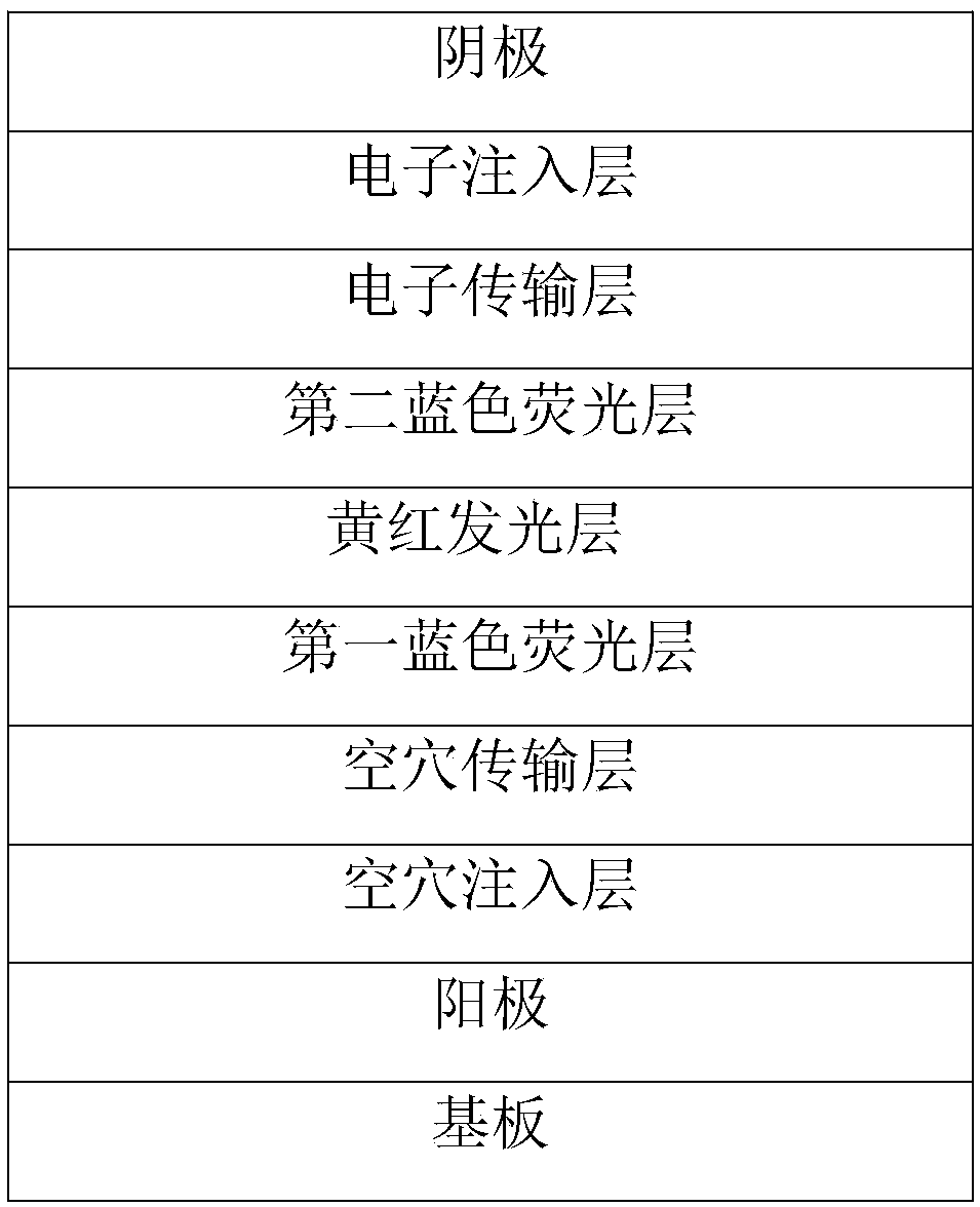
[0028] The structure of the prepared hybrid white organic electroluminescent device A with high efficiency and high color rendering index is: ITO / HAT-CN(100nm) / NPB(15nm) / TCTA(5nm) / 26DCzPPy:DDCzTrz(5nm,10 %) / 26DCzPPy:Ir(dmppy) 2 (dpp): Ir(piq)3(10nm,1:15%:1%) / 26DCzPPy:DDCzTrz(10nm,10%) / TmPyPB(50nm) / Cs 2 CO 3 (1nm) / Al(200nm).

[0029] A hybrid white light organic electroluminescent device A with high efficiency and high color rendering index of the present invention is prepared by the following method:

[0030] The structure of the device A is composed of the following layers from bottom to top:

[0031] Substrate, anode, hole injection layer, hole transport layer, first blue fluorescent layer, yellow-red phosphorescent layer, second blue fluorescent layer, electron transport layer, electron injection layer, cathode.

[0032] The aforementioned substrate is glass.

[0033] The above-mentioned anode is an ITO thin film.

[0034] The above-mentioned hole injection layer is a...

Embodiment 2

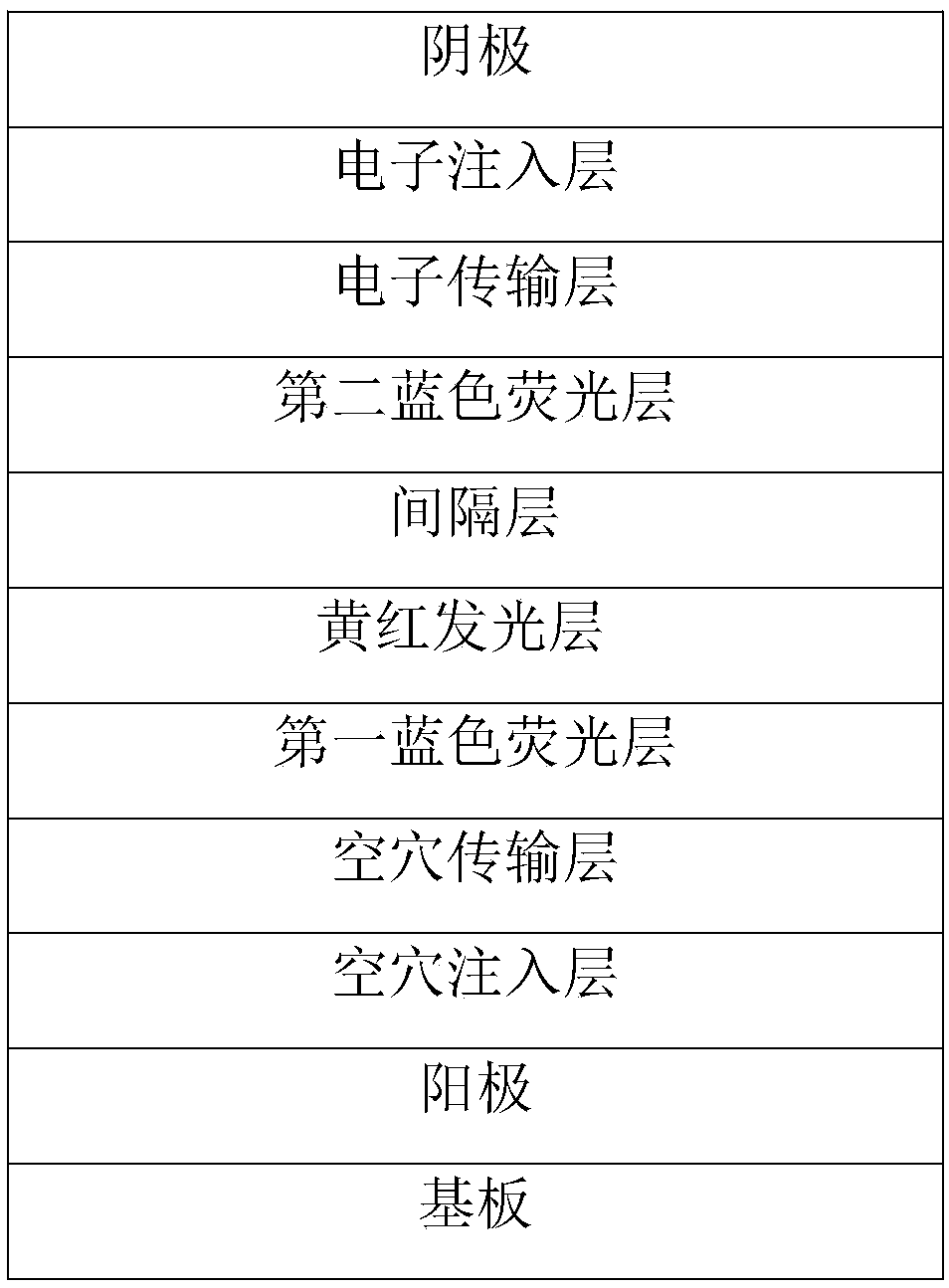
[0056] The difference between embodiment 2 and embodiment 1 is that a spacer layer is provided between the yellow-red light emitting layer and the second blue fluorescent layer.

Embodiment 3

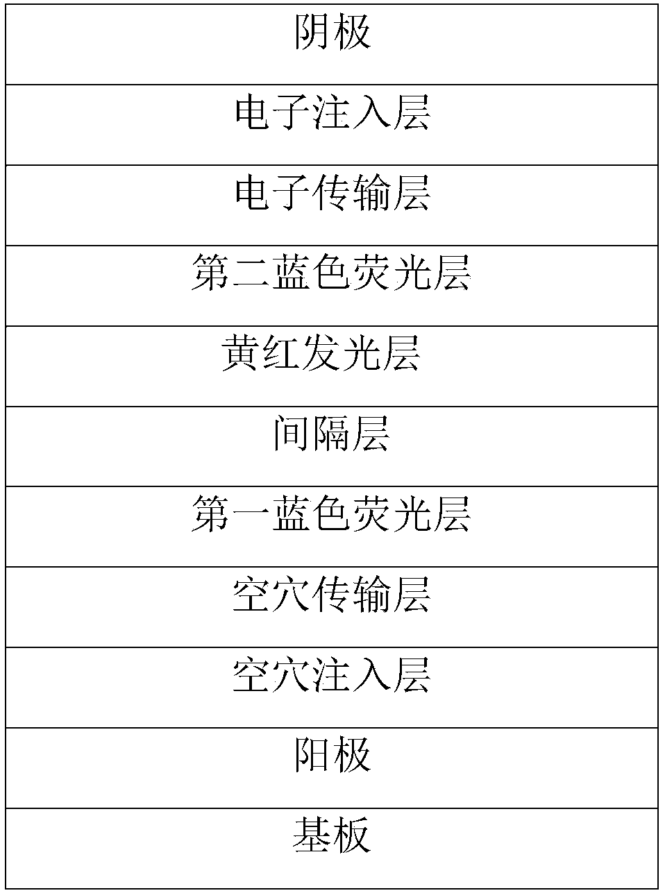
[0058] The difference between embodiment 3 and embodiment 1 is that a spacer layer is provided between the yellow-red light emitting layer and the first blue fluorescent layer.


PUM

PropertyMeasurementUnit
Thicknessaaaaaaaaaa
Thicknessaaaaaaaaaa

Abstract

The invention discloses a high-efficiency hybrid white OLED with a high color rendering index. The OLED comprises a substrate, an anode, a cavity implantation layer, a cavity transmission layer, a first blue fluorescent layer, a yellow and red phosphorescent layer, a second blue fluorescent layer, an electron transmission layer, an electron implantation layer and a cathode which are laminated successively from bottom to top; the yellow and red phosphorescent layer is formed by locating a yellow light material and a red light material in the same light emission layer; the first blue fluorescentlayer is arranged adjacent to the yellow and red light emission layer and separated from the yellow and red light emission layer by a spacing layer, the yellow and red phosphorescent layer is arranged adjacent to the second blue fluorescent layer and separated from the second blue fluorescent layer by a spacing layer, the concentration of red light emitted by the red light material is lower thanthe concentration of yellow light emitted by the yellow light material in the yellow and red light emission layer, and each of the first and second blue fluorescent layer is a non-doped or doped lightemission layer. The hybrid white OLED is high in efficiency and color rending index, simple in structure and convenient to popularize, can be popularized commercially, and has good market prospects.

Description

technical field [0001] The invention relates to the technical field of organic semiconductors, in particular to a hybrid white light organic electroluminescent device with high efficiency and high color rendering index. Background technique [0002] White OLED (Organic Light Emitting Diode) is a planar light-emitting device, which has the advantages of ultra-thin, large shape selectivity, suitable as a large-area light source, no need for heat dissipation, and simple processing. It is considered to be an ideal lighting source for the next generation. At the same time, white OLED can also replace ordinary LED light source, as the backlight source of modern mainstream liquid crystal display, realize ultra-thin liquid crystal display. White light OLED can also be combined with color filter film to realize color OLED display. Moreover, white light OLEDs can also be prepared into flexible devices to better serve human life. Therefore, white OLEDs have attracted more and more at...

Claims


Application Information

Patent Timeline
IPC IPC(8): H01L51/50H01L51/52H01L51/56
CPCH10K50/13H10K50/86H10K50/11H10K71/00
Inventor 罗东向陈其赞刘佰全张梦龙杨亿斌黄乐李京波
Owner GUANGDONG UNIV OF TECH
Learn More