

Thermal active delay fluorescent material and light-emitting device made with same
A technology of thermally activated delayed and fluorescent materials, applied in the application of the material in the field of organic electroluminescence, the field of small molecule organic electroluminescence materials, can solve the problem of high price, high price of phosphorescent materials, limited application space of phosphorescent materials, etc. problem, to achieve the effect of excellent device efficiency and high device efficiency
- Summary
- Abstract
- Description
- Claims
- Application Information
AI Technical Summary
Problems solved by technology
Method used
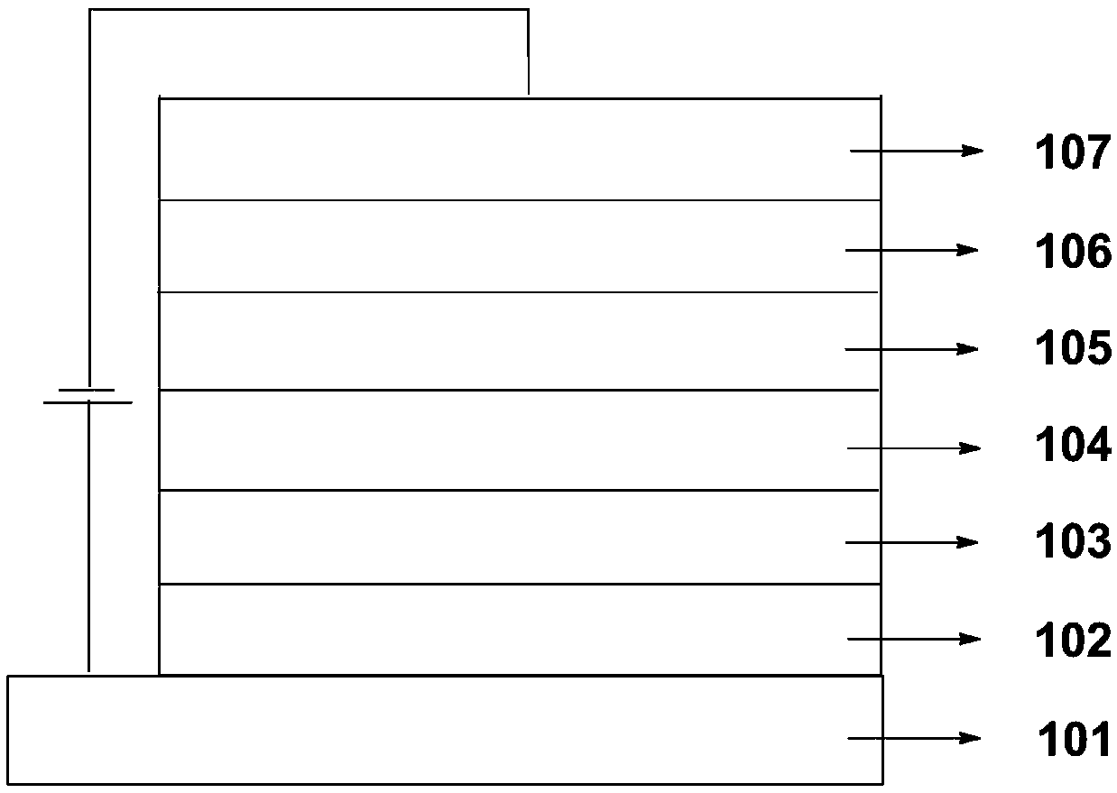
Image

Examples
Embodiment 1
[0039] The preparation of compound C01, reaction equation is as follows:
[0040]
[0041] The specific operation process is: in a 250mL three-necked flask, add compound A01 (2.18g, 0.004mol), carbazole (1.33g, 0.008mol), copper powder (0.65g, 0.01mol), potassium carbonate (1.38g, 0.01 mol), o-dichlorobenzene (80g), under the protection of nitrogen, the temperature was raised to 165°C, the temperature was kept for 36 hours, and the temperature was lowered to 45°C, 100g of tetrahydrofuran was added, suction filtered, 150g of tetrahydrofuran was rinsed, the filtrate was collected, and the solvent was removed under reduced pressure. The obtained solid was purified by silica gel column chromatography, and the eluent was dichloromethane:petroleum ether=1:1 (volume ratio). The obtained crude product of target C01 was further sublimated and purified using a chemical vapor deposition system at a sublimation temperature of 345° C. to obtain 1.1 g Target C01 fine product, yield 38.3%...
Embodiment 2
[0043] The preparation of compound C02, reaction equation is as follows:
[0044]
[0045] Using compound A02 as a raw material, refer to the method described in Example 1 to prepare compound C02, and obtain 1.0 g of the target object, high-resolution mass spectrometry, positive ion mode, molecular formula C49 h 28 N 2 o 3 , theoretical value 692.2100, test value 692.2105, elemental analysis (C 49 h 28 N 2 o 3 ), the theoretical value C: 84.95, H: 4.07, N: 4.04, O: 6.93, the measured value C: 84.96, H: 4.05, N: 4.02, O: 6.97, the ΔE of the compound C02 was measured using the simulation calculation method st is 0.043eV.
Embodiment 3
[0047] The preparation of compound C03, chemical equation is as follows:
[0048]
[0049] Referring to the method described in Example 1, compound C03 was prepared to obtain 0.96 g of the target object, high-resolution mass spectrum, positive ion mode, molecular formula C 54 h 38 N 2 o 2 , theoretical value 746.2933, test value 746.2931, elemental analysis (C 54 h 38 N 2 o 2 ), the theoretical value C: 86.85, H: 5.13, N: 3.75, O: 4.28, the measured value C: 86.86, H: 5.11, N: 3.72, O: 4.31, the ΔE of compound C03 was measured by the simulation calculation method st is 0.038eV.
PUM
| Property | Measurement | Unit |
|---|---|---|
| luminance | aaaaa | aaaaa |
| current efficiency | aaaaa | aaaaa |
| luminance | aaaaa | aaaaa |
Abstract
Description
Claims
Application Information