Supercharge Your Innovation With Domain-Expert AI Agents!

Signal detector

A detector and signal technology, applied in the field of signal detectors, can solve problems such as unfavorable design, influence, and difficulty in achieving amplifier symmetry

Active Publication Date: 2018-07-10
RICHWAVE TECH CORP
View PDF5 Cites 0 Cited by
  • Summary
  • Abstract
  • Description
  • Claims
  • Application Information

AI Technical Summary

Problems solved by technology

In order to increase the bandwidth, each stage amplifier can be selected as a high-bandwidth amplifier, but this will cause excessive power consumption
In addition, since the nodes of each stage of amplifiers correspond to different bandwidths, amplifiers with larger bandwidths should be selected for the later stage amplifiers, so it is difficult to achieve the symmetry of the amplifiers, which is not conducive to the design
In addition, when the gain of each amplifier is As, the gain of N amplifiers connected in series can be At, and the relationship can be At=(As) N , so the gain error (gain error) of amplifiers at all levels will accumulate step by step, resulting in the accuracy of gain being easily affected by temperature or process variation.

Method used


Image

  • Signal detector
  • Signal detector
  • Signal detector

Examples


Embodiment Construction

[0036] Specific embodiments of the present invention will be described in detail below in conjunction with the accompanying drawings. However, the present invention should be understood as not limited to such embodiments described below, and the technical idea of ​​the present invention can be implemented in combination with other known technologies or other technologies having the same functions as those known technologies.

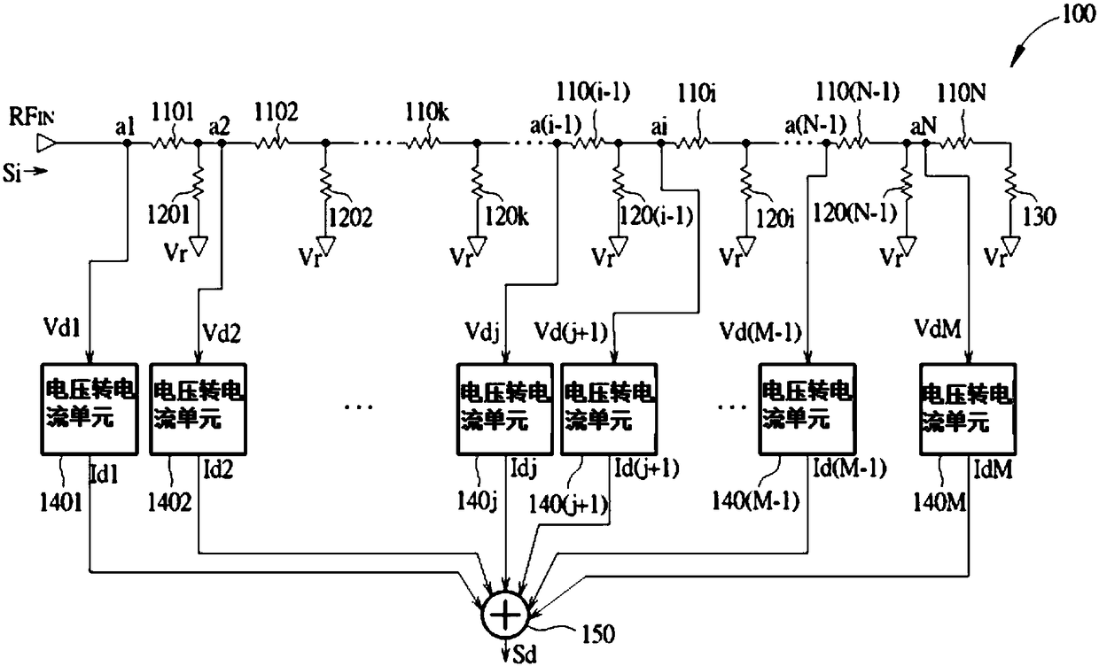
[0037] figure 1 is a schematic diagram of a signal detector 100 according to an embodiment of the present invention. The signal detector 100 may include a signal input terminal RF IN , N resistors 1101 to 110N, (N−1) resistors 1201 to 120 (N−1), resistor 130 , N nodes a1 to aN, voltage-to-current units 1401 to 140M, and bus unit 150 . The resistance values ​​of the resistors 1101 to 110N may be substantially the same, and the resistance values ​​of the resistors 1201 to 120 (N−1) may be substantially the same. The first end of the resistor 1101 is cou...


PUM


Abstract

The invention discloses a signal detector which includes a signal input terminal, N first resistors, (N-1) second resistors, a third resistor, M voltage-to-current units and a collection unit. A firstterminal of a 1st first resistor is coupled to the signal input terminal. A first terminal of an ith first resistor is coupled to a second terminal of an (i-1)th first resistor. A first terminal of akth second resistor is coupled to a second terminal of a kth first resistor. A second terminal of each second resistor is coupled to a reference voltage terminal. The third resistor is coupled between the reference voltage terminal and a second terminal of an Nth first resistor. Each voltage-to-current unit is coupled to a first terminal of a corresponding first resistor for converting a corresponding detection voltage to detection current. The collection unit is coupled to the M voltage-to-current units for generating a detection signal according to at least the M detection currents.

Description

technical field [0001] The present invention relates to a signal detector, in particular to a device that can receive a set of voltages at a set of nodes of a circuit, convert the set of voltages into a set of currents, and collect the set of currents to generate a detection signal signal detector. Background technique [0002] In the field of wireless communication, the performance of the receiver is crucial. Currently available receiver structures may include a group of amplifiers connected in a cascade structure, wherein the input end of the amplifier of the first stage may be connected to an antenna to receive a received signal. For example, when the amplifiers used are differential amplifiers, each amplifier may have two input terminals and two output terminals. According to the current receiver architecture, the two input terminals of each amplifier can be coupled to a corresponding rectifier, therefore, the existing receiver architecture can have multiple rectifiers...

Claims


Application Information

Patent Timeline
IPC IPC(8): H04B1/16
CPCH04B1/16G01R19/0092H03F1/02H03F3/04G01R19/00
Inventor 简惠庆
Owner RICHWAVE TECH CORP
Features
  • R&D
  • Intellectual Property
  • Life Sciences
  • Materials
  • Tech Scout
  • Unparalleled Data Quality
  • Higher Quality Content
  • 60% Fewer Hallucinations
Learn More