Chemical plant waste gas treatment apparatus

A technology for waste gas treatment devices and chemical plants, applied in the direction of gas treatment, combined devices, air quality improvement, etc., can solve the problems of insufficient treatment, single function, complex structure of the waste gas treatment system, etc., to achieve compact structure, prevent air pollution, Easy to install

Inactive Publication Date: 2018-07-13
潘建平
View PDF0 Cites 5 Cited by
  • Summary
  • Abstract
  • Description
  • Claims
  • Application Information

AI Technical Summary

Problems solved by technology

[0004] With the advancement of science and technology, factories and the country have higher and higher requirements for waste emissions. The traditional waste gas treatment sy

Method used


Image

  • Chemical plant waste gas treatment apparatus
  • Chemical plant waste gas treatment apparatus
  • Chemical plant waste gas treatment apparatus

Examples


Embodiment Construction

[0019] The technical solutions in the embodiments of the present invention will be clearly and completely described below in conjunction with the accompanying drawings in the embodiments of the present invention. Obviously, the described embodiments are only a part of the embodiments of the present invention, rather than all the embodiments. Based on the embodiments of the present invention, all other embodiments obtained by those of ordinary skill in the art without creative work shall fall within the protection scope of the present invention.

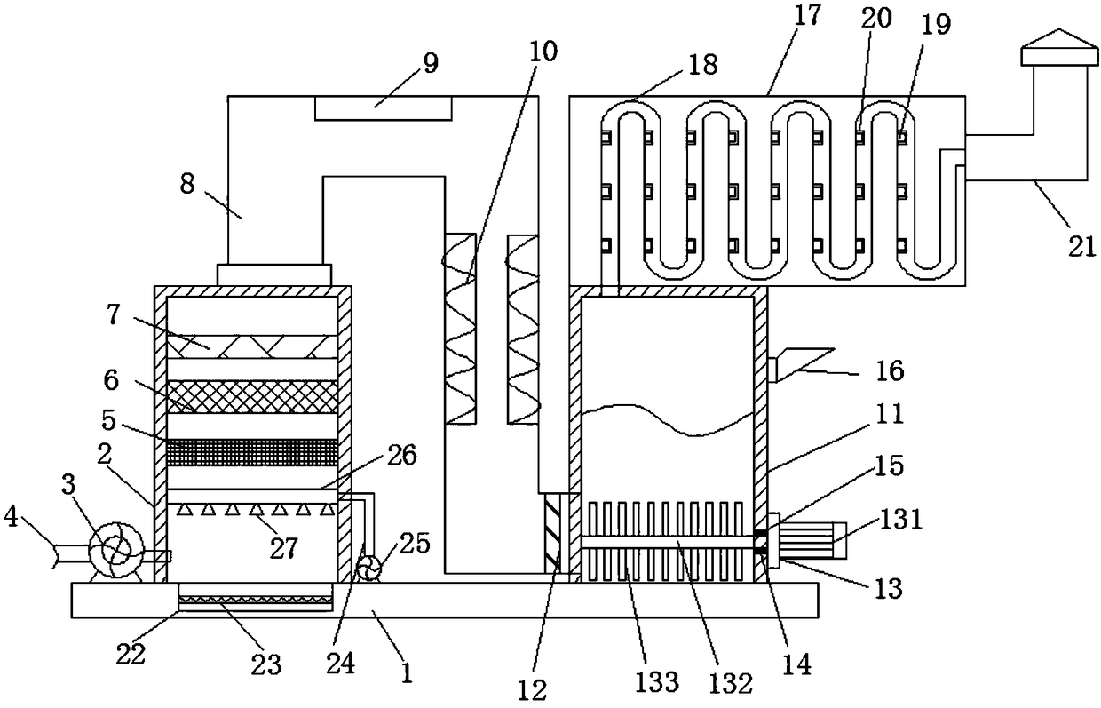
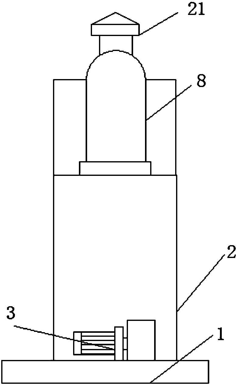
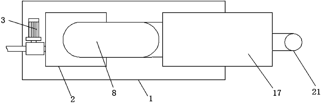
[0020] See Figure 1-3 , The present invention provides a technical solution: the chemical plant waste gas treatment device includes a base 1, the top end of the base 1 is welded with a sedimentation tank 2, and the bottom side of the sedimentation tank 2 is provided with a blower 3, the blower The bottom of the blower 3 is installed on the top of the base 1, the air inlet of the blower 3 is welded with an air inlet pipe 4, and the air o...


PUM


Abstract

The invention discloses a chemical plant waste gas treatment apparatus, comprising a base. A settling tank is welded to one end of the top of the base. A blower is arranged on one side of the bottom of the settling tank. The bottom of the blower is mounted at the top of the base. An intake port of the blower is provided with an intake pipe by welding. An exhaust port of the blower is communicatedwith an intake port in one side of the bottom of the settling tank; a spray pipe is welded to the inner bottom end of the settling tank, and the bottom of the spray pipe is communicated with a nozzle.The chemical plant waste gas treatment apparatus is compact in structure and simple to mount, and ensures sufficiency of waste gas treatment as adsorbing, settling, filtering and disinfecting are integrated herein; the exhaust pipe is set to an S-shaped coil exhaust pipe, waste gas can be fully disinfected, air pollution is prevented, and emission safety is ensured for waste gas; the chemical plant waste gas treatment apparatus is special for treatment of waste gas and is widely applicable to the field of waste gas emission for chemical plants.

Description

Technical field [0001] The invention relates to the technical field of waste gas treatment in a chemical plant, in particular to a chemical plant waste gas treatment device. Background technique [0002] Chemical grease processing usually has a heating process. The low temperature requires more than 100 degrees, and the high temperature even reaches hundreds of degrees. A large amount of waste gas will inevitably be generated during the production of grease. Because there are many substances harmful to the environment in the waste gas, it is directly Emissions will cause air pollution, so companies need to strictly treat production waste gas, and discharge only when they meet environmental protection requirements. [0003] General waste gas treatment includes organic waste gas treatment, dust waste gas treatment, acid and alkali waste gas treatment, odor waste gas treatment, and air sterilization, disinfection and purification. Waste gas treatment can effectively remove organic wa...

Claims


Application Information

Patent Timeline
IPC IPC(8): B01D50/00B01D53/84B01D53/78B01D53/74B01D53/48B01D53/58B01D53/72
CPCB01D53/48B01D53/58B01D53/72B01D53/74B01D53/78B01D53/84B01D2257/304B01D2257/302B01D50/60Y02A50/20
Inventor 潘建平
Owner 潘建平
Why Eureka
Try Eureka