Pipefitting screening device

A technology for screening devices and pipe fittings, which is applied in the direction of solid separation, classification, chemical instruments and methods, etc., can solve the problems of high labor intensity of workers, and achieve the effect of reducing labor intensity

Active Publication Date: 2018-07-13
徐州第三纺织有限公司
View PDF4 Cites 4 Cited by
  • Summary
  • Abstract
  • Description
  • Claims
  • Application Information

AI Technical Summary

Problems solved by technology

[0005] The present invention intends to provide a pipe fitting screening device to solve the problem in the prior art that the pipe fittings need to be manually moved, which makes the labor intensity of the workers high

Method used


Image

  • Pipefitting screening device
  • Pipefitting screening device

Examples


Embodiment Construction

[0025] Further detailed explanation through specific implementation mode below:

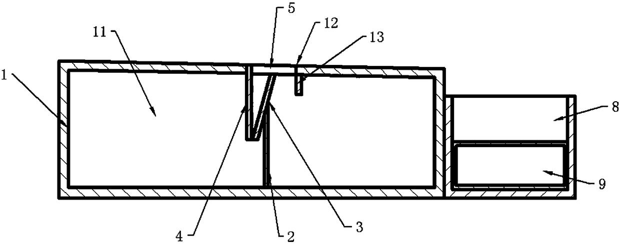
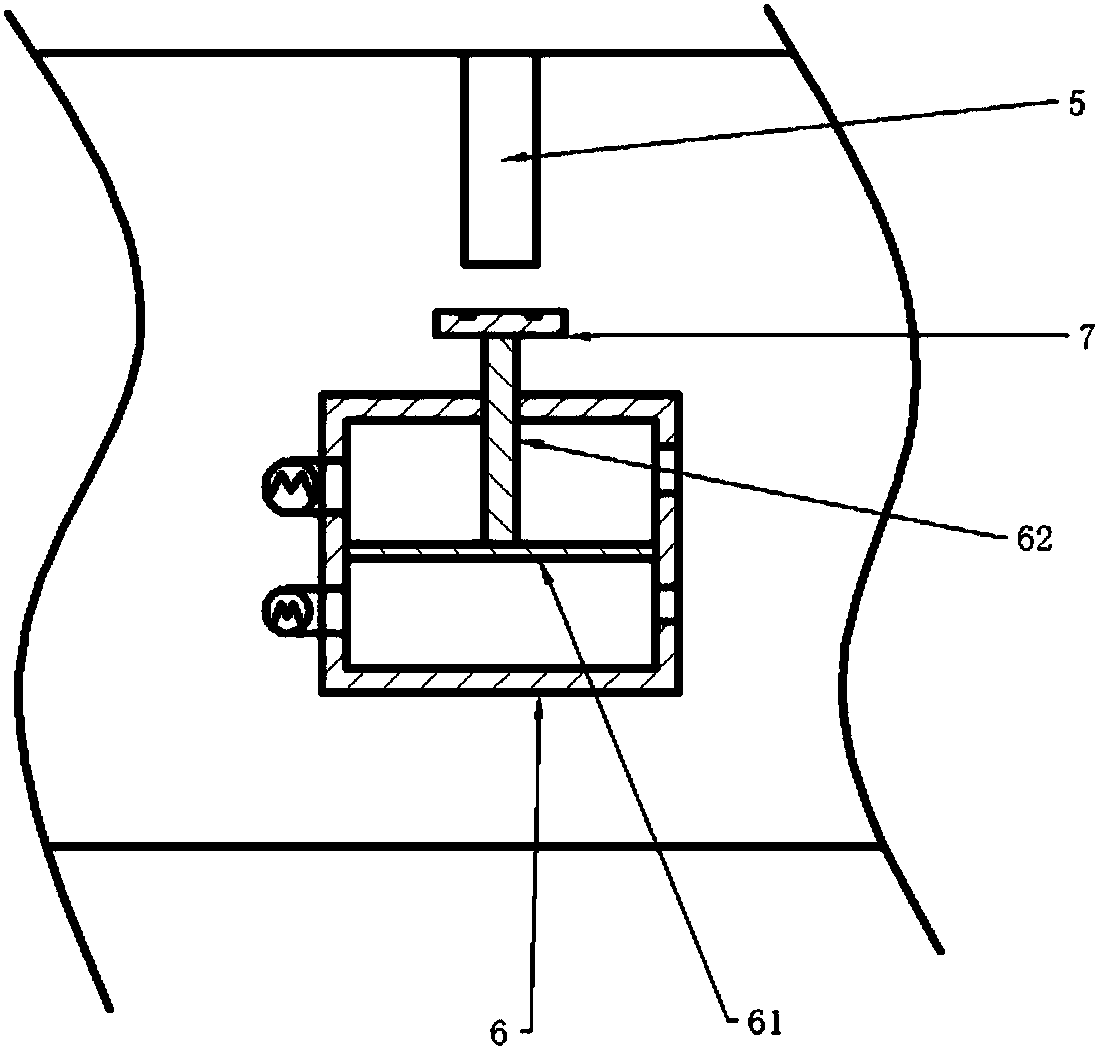
[0026] The reference signs in the drawings of the description include: workbench 1, cavity 11, screening tank 12, limit block 13, support column 2, pole 3, baffle plate 4, support block 5, piston barrel 6, piston 61, Piston rod 62, magnet block 7, collection box 8, air bag 9.

[0027] The embodiment is basically as attached figure 1 Shown:

[0028] A pipe fitting screening device, comprising a workbench 1 with an inclined upper surface, the left end of the workbench 1 is a feed end, the right end of the workbench 1 is a discharge end, the feed end of the workbench 1 is higher than the discharge end, and The inclination angle of the upper surface of the workbench 1 is 5°; the feed end of the workbench 1 is provided with a material guide plate. The right end of the workbench 1 is provided with a material receiving box, and the receiving box is provided with an air bag 9, and the air bag 9 is pro...


PUM


Abstract

The invention belongs to the technical field of tubular object screening equipment, and discloses a pipefitting screening device. The device comprises a worktable, a cavity is formed in the worktable,a screening groove is formed in the worktable, a supporting column is arranged in the cavity, a supporting rod is hinged to the supporting column, a baffle is arranged at one end of the supporting rod, a supporting block is arranged at the other end of the supporting rod, a sucking mechanism is arranged on the worktable, and comprises a piston cylinder with two closed ends, a piston is in slidingconnection into the piston cylinder, a piston rod is arranged on the piston, a magnet block is arranged on the piston rod, a first air inlet and a second air outlet are formed in the end, away from the piston rod, of the piton in the piston cylinder, a first air inlet pump is connected of the first air inlet, a second air inlet and a second air outlet are formed in the end, close to the piston rod, in the piston cylinder, and a second air inlet pump is connected to the second air inlet. The problems that in the prior art, pipefitting needs to be manually carried, and labor intensity of workers is large are solved.

Description

technical field [0001] The invention belongs to the field of tubular object screening equipment, and in particular relates to a pipe fitting screening device. Background technique [0002] Pipe fittings refer to the general designation of parts in the pipeline system that play the roles of connection, control, direction change, flow diversion, sealing and support. In machining, it is usually necessary to use a large number of pipe fittings with consistent dimensions. The pipe fittings of the same batch have basically the same length after processing, but when making the pipe fittings, due to the operation of the equipment, the wall thickness of the pipe fittings will be inconsistent, which will lead to differences in the weight of the pipe fittings. In many machining processes, there are certain requirements for the weight of the device, so heavy pipe fittings cannot be used for processing. Excessive pipe fittings need to be screened out before use. [0003] At present, f...

Claims


Application Information

Patent Timeline
Patent Type & Authority Applications(China)
IPC IPC(8): B07B13/08B07B13/16
CPCB07B13/08B07B13/16
Inventor 王如君
Owner 徐州第三纺织有限公司
Why Eureka
Try Eureka