[0014] The technical solutions in the embodiments of the present invention will be clearly and completely described below in conjunction with the accompanying drawings in the embodiments of the present invention. Obviously, the described embodiments are only a part of the embodiments of the present invention, rather than all the embodiments. Based on the embodiments of the present invention, all other embodiments obtained by those of ordinary skill in the art without creative work shall fall within the protection scope of the present invention.
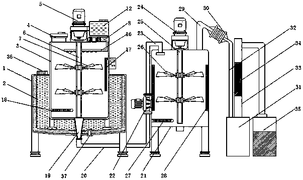
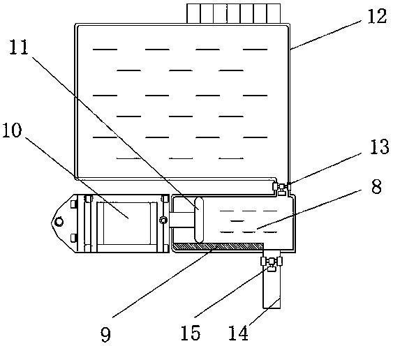
[0015] See Figure 1-2 , An embodiment provided by the present invention: a para-fluorotoluene mechanical device, comprising a freezing point control chamber 1, characterized in that: the inner wall of the freezing point control chamber 1 is provided with a heat insulation layer 2, and the freezing point control chamber 1 A first reactor 3 is installed inside, and the upper end of the first reactor 3 penetrates through the freezing point control warehouse 1 and extends to the top of the freezing point control warehouse 1, and the side above the first reactor 3 is equipped with a feed inlet 4, A first servo motor 5 is installed at the middle position above the first reaction kettle 3. The model of the first servo motor 5 can be YS90-2. The output end of the first servo motor 5 is installed with a first rotating shaft 6, a first rotating shaft 6 It penetrates the first servo motor 5 and extends to the inside of the first reactor 3, and the outer side of the first rotating shaft 6 is equidistantly installed with two sets of first blades 7, and the upper part of the freezing point control chamber 1 is away from the feeding port 4 A conveying tank 8 is installed. A pressure sensor 9 is installed below the inside of the conveying tank 8. A pneumatic cylinder 10 is installed on the side of the conveying tank 8 close to the feed port 4, and the output end of the pneumatic cylinder 10 penetrates the conveying tank 8 and a plug plate 11 is installed. , Sodium nitrite 12 is installed above the conveying tank 8, and the sodium nitrite 12 is connected to the conveying tank 8, and a first valve 13 is installed at the connecting place. A first water pipe is installed on the side of the conveying tank 8 away from the feed inlet 4 14. A second valve 15 is installed at one end of the first water pipe 14 close to the delivery tank 8, and a uniform pipe 16 is installed at the end of the first water pipe 14 away from the delivery tank 8. The delivery tank 8 communicates with the uniform pipe 16 through the second valve 15 , The first reactor 3 is installed at the top of the side far away from the feed port 4 with an acid-base detection helper 17, and the inside of the first reactor 3 is installed below the side near the feed port 4 with a first thermometer 18, the first reactor A discharge port 19 is installed below 3, and the discharge port 19 penetrates the freezing point control bin 1 and extends below the freezing point control bin 1. A first conveying pipe 20 is installed below the discharge port 19, and the freezing point control bin A second reactor 21 is installed on one side of 1, and a water pump 22 is installed on the side of the second reactor 21 close to the freezing point control warehouse 1. The input end of the water pump 22 is connected to the freezing point control warehouse 1 through the first delivery pipe 20 , The output end of the water pump 22 is equipped with a second delivery pipe 23, which communicates with the second reactor 21 through the second delivery pipe 23, and a second servo motor 24 is installed at the middle position above the second reactor 21. The model of the servo motor 24 can be YS90-2. The output end of the second servo motor 24 is equipped with a second rotating shaft 25. The second rotating shaft 25 penetrates the second reactor 21 and extends to the inside of the second reactor 21, and the second rotating shaft A second blade 26 is installed equidistantly on the outside of the second reactor 21, a second thermometer 27 is installed below the side of the second reactor 21 close to the freezing point control chamber 1, and heating plates are installed symmetrically on both sides of the second reactor 21 28. A first condenser tube 29 is installed on the side of the second reactor 21 far away from the freezing point control chamber 1, and a condenser 30 is installed on the end of the first condenser tube 29 away from the second reactor 21. The second reactor 21 A rectification tower 31 is installed on the side far away from the freezing point control bin 1, and a second condenser pipe 32 is installed on the end of the condenser 30 far away from the freezing point control bin 1 , The condenser 30 is connected to the second condenser pipe 32 through the rectification tower 31, a reactor tower 33 is arranged above the rectification tower 31, a packing layer 34 is arranged inside the reactor tower 33, and the rectification tower 31 is far away from the freezing point control chamber 1. A finished product collection tank 35 is installed on one side of the reactor, and the kettle tower 33 is connected to the finished product collection tank 35 through a pipeline.
[0016] In this implementation: a sealing cover 36 is installed above the freezing point control bin 1 on the side close to the inlet 4, and coarse salt and ice can be added to the freezing point control bin 1 through the sealing cover 26 to reduce the reaction temperature and improve efficiency The water outlet 37 of the freezing point control silo is installed on the side of the freezing point control bin 1 far from the inlet 4 to facilitate the discharge of the melted liquid. The inner edge of the 4 is equipped with a sealing rubber ring to improve the sealing performance of the device. The first blade 7 and the second blade 26 are made of stainless steel anti-corrosion material, which can increase the service life of the blades and prevent corrosion by the solution. The large friction with the ground makes the device more stable.
[0017] Working principle: When in use, first connect the device to the power supply, add p-toluidine and 40% hydrofluoric acid from the feed port 4 to the first reaction vessel 3, and then add the p-toluidine and 40% hydrofluoric acid to the inside of the freezing point control chamber 1 from the sealing cover 36 Ice cubes and coarse salt use the principle of lower freezing point of the salt solution and cool down to maintain the temperature in the first reactor. The heat insulation layer 2 prevents heat exchange between the first reactor 3 and the outside world, and then turns on the first servo motor 5 Drive the first blade 7 to rotate, stir toluidine and hydrofluoric acid to speed up the reaction. After the reaction is complete, open the first valve 13 to let the sodium nitrite solution fall into the delivery tank, and monitor the nitrous acid through a pressure sensor. Input the amount of sodium solution, then open the air cylinder 10, and deliver the sodium nitrite solution to the uniform pipe 16 through the stopper plate 11, and evenly add it to the reactants through the holes on it, and produce diazonium compounds after a period of reaction , Wherein the pH value and temperature inside the kettle body can be detected by the acid-base detection rod 17 and the first thermometer 18, and then the water pump 22 is turned on to deliver the diazonium compound to the second reactor 21, and the heating plate 28 is turned on The diazo compound is heated, and the second servo motor 24 is turned on at the same time to drive the second blade 26 to rotate, stir it, and finally generate a parafluorotoluene solution. After the temperature continues to rise, the parafluorotoluene solution evaporates, passes through the condenser 30 and is condensed to In the rectification still 31, the impurities in the para-fluorotoluene solution are filtered through the packing on the rectification still 31 and collected.