
Valve tightness detecting device

A sealing detection and valve technology, which is applied in the direction of liquid tightness measurement using liquid/vacuum degree, and detecting the appearance of fluid at the leakage point, etc., can solve the problem of affecting detection efficiency, increasing detection workload, and easily causing false detection, etc. problem, to achieve the effect of improving detection efficiency, facilitating automatic paving, and improving accuracy

Active Publication Date: 2018-07-13
重庆新锐科技服务有限公司
View PDF7 Cites 10 Cited by
  • Summary
  • Abstract
  • Description
  • Claims
  • Application Information

AI Technical Summary

Problems solved by technology

However, the problems of this detection method mainly include: (1) Frequent installation of valves increases the detection workload and affects the detection efficiency; (2) It mainly relies on the naked eye to observe whether there is water in the other water pipe, and the conclusion accuracy is not high. easy to cause false detection

Method used


Image

  • Valve tightness detecting device
  • Valve tightness detecting device
  • Valve tightness detecting device

Examples


Embodiment Construction

[0022] The present invention will be described in further detail below by means of specific embodiments:

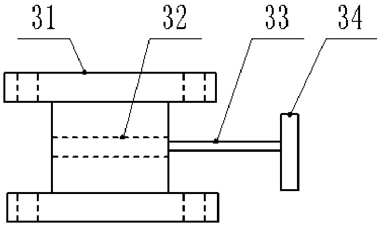
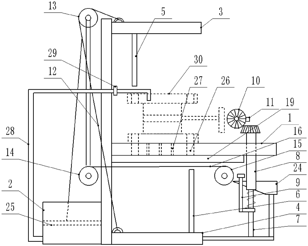
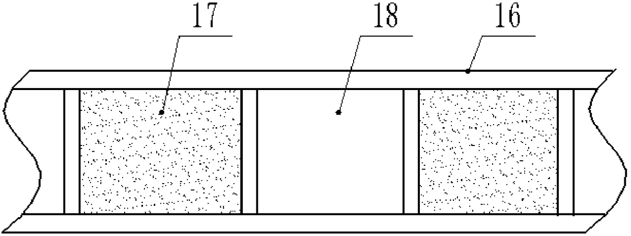
[0023] The reference signs in the drawings of the description include: detection table 1, iodine solution tank 2, first pressing plate 3, second pressing plate 4, first inserting rod 5, second inserting rod 6, lead screw 7, lead screw pair 8, Magnetic rod 9, auxiliary bevel gear 10, push tooth 11, pull cord 12, fixed pulley 13, first runner 14, second runner 15, tape 16, glutinous rice paper 17, gap 18, drain plate 19, through Hole 20, drain tank 21, drain hole 22, plugging ball 23, conical bucket 24, filter plate 25, socket 26, leak hole 27, liquid pipe 28, switch 29, valve 30, valve body 31, valve Core 32, valve stem 33, hand wheel 34.

[0024] Example figure 2 Shown: a valve sealing detection device, including a detection platform 1, a frame is provided on the left side of the detection platform 1, and a horizontal first pressure plate 3 and a second pressure plate ...


PUM


Abstract

The invention relates to the valve detection processing field, and discloses a valve tightness detecting device. The valve tightness detecting device comprises a detecting table and an iodine solutionbox; a frame is arranged on the detecting table, a first pressing plate and a second pressing plate are glidingly connected to the frame, and a pull rope is connected to the middle of the first pressing plate and the second pressing plate; a fixed pulley, a first rotary wheel and a second rotary wheel are rotationally connected to the frame; the pull rope strides over the fixed pulley, the firstrotary wheel is connected with the second rotary wheel through a belt; a roll belt are wound between the first rotary wheel and the second rotary wheel, and a wafer is arranged on the roll belt; a first plug rod is connected to the first pressing plate, and a second plug rod is connected to the second pressing plate; plug holes are arranged at the parts where the detecting table is faced to the first plug rod and the second plug rod; a detecting site is arranged between two plug holes, and provided with a fluid leaking hole; the iodine solution box is connected with a fluid pipe, a free end ofthe fluid pipe is located at the upper part of the detecting site, a switch is arranged on the fluid pipe and connected with a torsional spring. Through the invention, the detecting efficiency and accuracy of the valve can be improved.

Description

technical field [0001] The invention relates to the field of valve detection and processing, in particular to a valve sealing performance detection device. Background technique [0002] The valve is a control component in the fluid delivery system, which has functions such as cut-off, adjustment, flow diversion, reverse flow prevention, pressure stabilization, flow diversion or overflow pressure relief. The main structure of the valve is as figure 1 As shown, including the valve body, valve core, valve stem and handwheel, the valve has a T-shaped structure as a whole, while the valve body has an "I"-shaped structure, and the valve body includes an intermediate pipe and flanges connected at both ends of the intermediate pipe. The flange is provided with a plurality of positioning holes evenly distributed in the circumferential direction, while the handwheel includes a wheel ring and a connecting column in the wheel ring. [0003] After the production and processing of the v...

Claims


Application Information

Patent Timeline
IPC IPC(8): G01M3/22
Inventor 罗贵良
Owner 重庆新锐科技服务有限公司
Learn More