Anti-DC component current transformer error tester and test method thereof
A current transformer and anti-DC technology, applied in the error tester of anti-DC component current transformer based on half-wave rectification and its testing field, can solve problems such as low inspection efficiency, and achieve wide current range coverage and large output capacity. , the effect of accuracy and stability assurance
- Summary
- Abstract
- Description
- Claims
- Application Information
AI Technical Summary
Problems solved by technology
Method used
Image
Examples
Embodiment 1
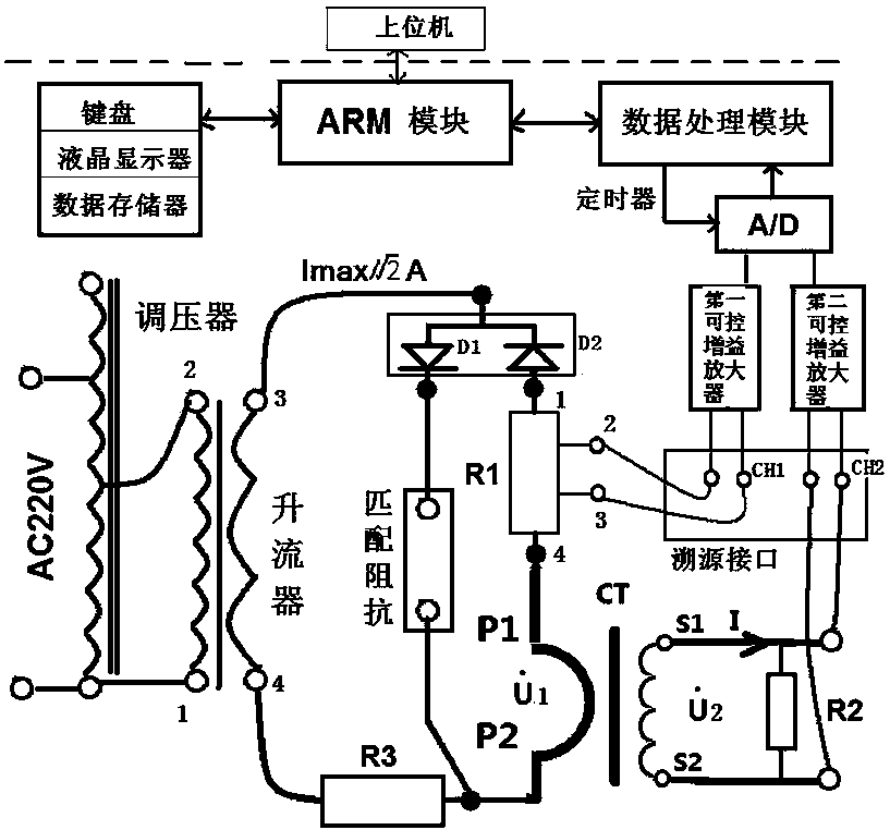
[0043] Embodiment 1: as attached figure 1 As shown, the anti-DC component current transformer error tester based on half-wave rectification includes a housing, an anti-DC component current transformer test circuit and a data processing unit, and the anti-DC component current transformer test circuit and data processing unit are both Set in the casing, the anti-DC component current transformer test circuit includes a voltage regulator, a current booster, a first rectifier diode D1, a second rectifier diode D2, a current limiting resistor R3, a first half-wave current sampling resistor R1, a second A half-wave current sampling resistor R2, the input end of the voltage regulator is connected to an external AC power supply, the output end of the voltage regulator is respectively connected to the first terminal and the second terminal of the current booster, and the third terminal of the current booster is respectively connected to the The anode of the first rectifier diode D1 conn...
Embodiment 2
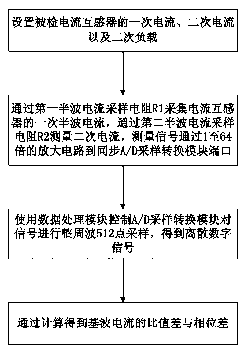
[0056] Embodiment 2: as figure 2 Shown, a kind of test method based on the above-mentioned anti-dc component current transformer error tester under half-wave rectification comprises the following steps:
[0057] Step 1, set the primary current, secondary current and secondary load of the anti-DC component current transformer;
[0058] Step 2, collect the primary half-wave current I of the current transformer through the first half-wave current sampling resistor R1 1 , through the second half-wave current sampling resistor R2 to measure the secondary current I 2 , the measurement signal is amplified by the first controllable gain amplifier and the second controllable gain amplifier from 1 to 64 times, and then synchronized to the port of the A / D sampling conversion module, so that the measurement signal is between 1.2V and 2.5V, and the peak voltage is less than 4V , within the linear interval of the A / D sampling conversion module;
[0059] Step 3, use the data processing m...
Embodiment 3
[0077] Embodiment 3: as shown in table 1, adopt the measurement data that the test method of standard current transformer and DC power source obtains to compare with the present invention, measurement data deviation is less than 1 / 3 of current transformer half-wave error limit. Table 1 shows the measurement data of two half-wave rectification error measurement schemes for the same current transformer.
[0078] It can be seen from Table 1 that two different test devices test the same current transformer, and the results obtained are less than 1 / 3 of the error limit of level 3 or level 6 required by the standard, and the performance of the present invention is verified.
[0079] Compared with the detection method of half-wave rectification (DC and even harmonics), according to the analysis of a large number of test data, the fundamental wave ratio difference Δf of qualified current transformers in the state of half-wave rectification is basically between -1.0% and 2.5%. , the an...
PUM
 Abstract
Description
Claims
Application Information
 - R&D
- Intellectual Property
- Life Sciences
- Materials
- Tech Scout
- Unparalleled Data Quality
- Higher Quality Content
- 60% Fewer Hallucinations
Browse by: Latest US Patents, China's latest patents, Technical Efficacy Thesaurus, Application Domain, Technology Topic, Popular Technical Reports.
© 2025 PatSnap. All rights reserved.Legal|Privacy policy|Modern Slavery Act Transparency Statement|Sitemap|About US| Contact US: help@patsnap.com


