Design method of a rotating shaft optical adjustment mount

A technology of optical adjustment frame and design method, which is applied in the direction of optics, optical components, instruments, etc., can solve the problems of poor anti-seismic ability of optical adjustment frame, only limited to fine-tuning of angle, and change of center position, so as to improve anti-seismic ability, eliminate movement, The effect of eliminating adjustment errors

Active Publication Date: 2019-12-03
SHANGHAI INST OF OPTICS & FINE MECHANICS CHINESE ACAD OF SCI
View PDF5 Cites 0 Cited by
  • Summary
  • Abstract
  • Description
  • Claims
  • Application Information

AI Technical Summary

Problems solved by technology

Although the two adjustment methods can better adjust the angle, pitch and yaw direction, but because the adjustment knobs of some existing optical adjustment mounts are on the side, when it is required to build a relatively compact optical path, it will make subsequent optical path adjustments difficult. bring some difficulties
At the same time, for the non-coplanar optical adjustment mount, there is also the problem that the center position of the optical element (mirror surface) changes when the optical adjustment mount is adjusted
Moreover, most of today's optical adjustment mounts are composed of a movable plate (connecting the optical elements), a fixed plate, a steel ball (for supporting), a screw (for adjusting the movable plate relative to the fixed plate), and a spring (for stretching) The optical adjustment mount with this structure has poor shock resistance and is limited to fine-tuning the angle

Method used

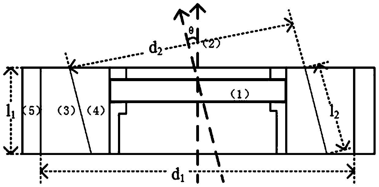
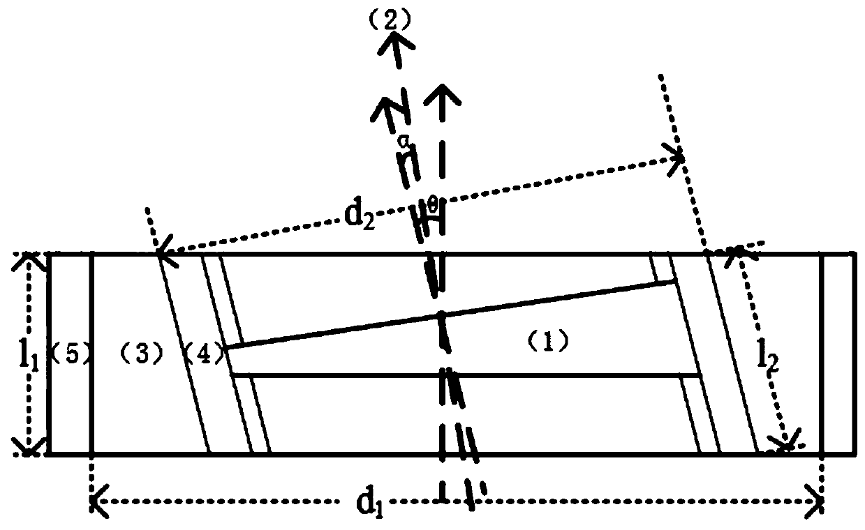
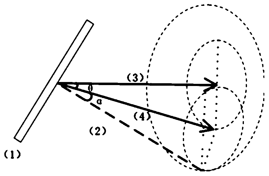

Image

  • Design method of a rotating shaft optical adjustment mount
  • Design method of a rotating shaft optical adjustment mount
  • Design method of a rotating shaft optical adjustment mount

Examples


Embodiment Construction

[0022] The present invention will be further described below in conjunction with the accompanying drawings and embodiments.

[0023] We explain the design of the rotating shaft optical adjustment mount theoretically and with examples.

[0024] We illustrate the pitch and yaw of the plane mirror normal based on this design.

[0025] Such as image 3 As shown, if the second rotating cylinder 4 is rotated first, it turns around its own rotation axis through an angle Since the second rotating cylinder 4 is contained in the first rotating cylinder 3, only the second rotating cylinder 4 and the reflector 1 rotate, and the first rotating cylinder 3 does not move; then the second rotating cylinder 4 is not adjusted, and the first rotating cylinder is adjusted cylinder 3, so that it rotates through an angle around its own axis of rotation At this moment, all the devices in the first rotating cylinder 3 rotate with it, including the second rotating cylinder 4 and the reflecting mir...


PUM


Abstract

The invention discloses a design method of a rotating shaft type optical adjustment frame. The rotation axis of the optical lens fixed by the adjustment frame forms a certain angle with the normal line of the optical mirror surface. When the fixed lens unit rotates, the normal line of the mirror surface also rotates. The structure realizes double-layer rotation, and can adjust the mirror normal to any position of a certain spatial solid angle, realizing an effective two-dimensional light adjustment method.

Description

technical field [0001] The invention relates to the principle design of the optical adjustment frame. The rotation axis of the optical lens fixed by the adjustment frame forms a certain angle with the normal line of the optical mirror surface. , the mirror normal can be adjusted to any position of a certain spatial solid angle, and an effective two-dimensional light adjustment method can be realized. Background technique [0002] The adjustment of the plane mirror is very important in the optical path. At present, two-dimensional adjustments (angle pitch and yaw directions) of optical components are generally carried out in two ways: non-coplanar adjustment and coplanar adjustment. Although the two adjustment methods can better adjust the angle, pitch and yaw direction, but because the adjustment knobs of some existing optical adjustment mounts are on the side, when it is required to build a relatively compact optical path, it will make subsequent optical path adjustments d...

Claims


Application Information

Patent Timeline
Patent Type & Authority Patents(China)
IPC IPC(8): G02B27/00G02B7/182
CPCG02B7/182G02B27/0012
Inventor 王倩魏荣王文丽王育竹
Owner SHANGHAI INST OF OPTICS & FINE MECHANICS CHINESE ACAD OF SCI
Why Eureka
Try Eureka