Rotor position angle compensation method of motor vector control

A technology of rotor position and vector control, which is applied in vector control system, motor generator control, electronic commutation motor control, etc. It can solve the problems that the motor control performance cannot be improved well, and there are large errors, so as to improve the current The effect of controlling precision and enhancing dynamic performance

Active Publication Date: 2018-07-13
SHANGHAI SIGRINER STEP ELECTRIC
View PDF3 Cites 22 Cited by
  • Summary
  • Abstract
  • Description
  • Claims
  • Application Information

AI Technical Summary

Problems solved by technology

[0004] 1) The compensation time is fixed at 1.5Ts (Ts is a PWM cycle), and there may be a large error in this time;
[0005] 2) Compensating only the inverse coordinate transformation angle does not improve the motor control performance under high-speed motor conditions.

Method used


Image

  • Rotor position angle compensation method of motor vector control
  • Rotor position angle compensation method of motor vector control
  • Rotor position angle compensation method of motor vector control

Examples


Embodiment Construction

[0014] The present invention will be further described below in conjunction with the accompanying drawings.

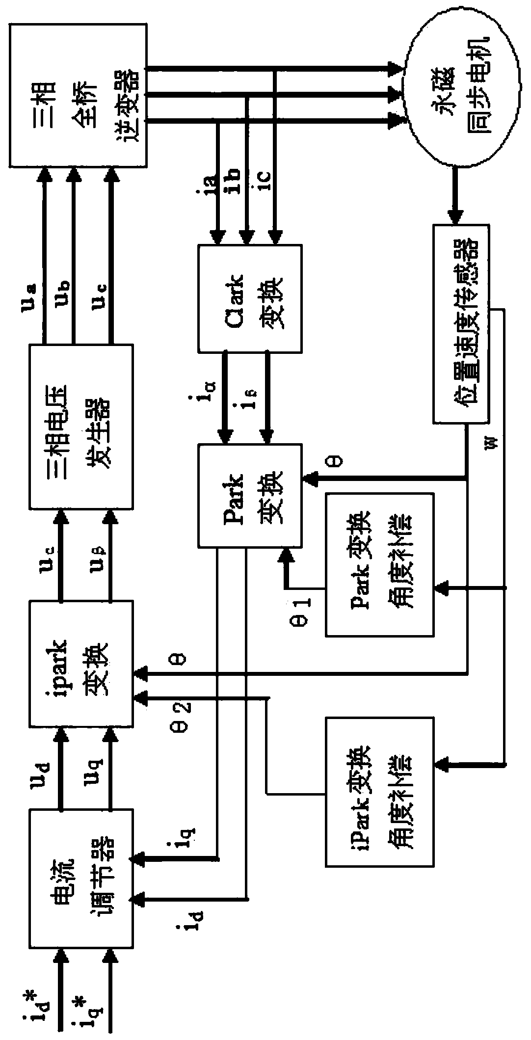
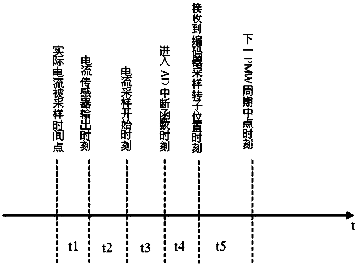
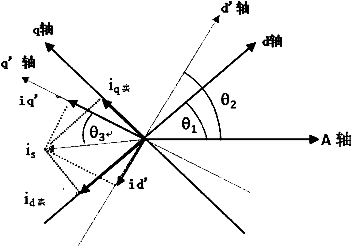
[0015] A rotor position angle compensation method for motor vector control according to an embodiment of the present invention, wherein, in motor vector control, the controller compensates the rotor position angle θ sampled by the rotor position detection device, and according to the compensated rotor position Angle θ' to α-axis feedback current i α and β-axis feedback current i β Perform Park transformation to obtain the actual d-axis current i of the motor d and q-axis actual current i q , where, θ'=θ-θ1, θ1=w*(t1+t2+t3+t4), θ1 is the Park transformation compensation angle, w is the motor operating frequency, t1 is the delay time of the current sensor used to sample the stator current , t2 is the delay time of the filter circuit for filtering the output signal of the current sensor, t3 is the time between the start of sampling the stator current by the AD peripher...


PUM


Abstract

The invention relates to a rotor position angle compensation method of motor vector control. A rotor position angle Theta obtained by sampling is compensated by a controller, Park conversion is performed on the compensated rotor position angle Theta', Theta'=Theta-Theta1, Theta1=w*(t1+t2+t3+t4), Theta1 is a Park conversion compensation angle, w is a running frequency of the motor, t1 is delay timeof a current sensor for sampling a stator current, t2 is delay time of a filtering circuit for filtering an output signal of the current sensor, t3 is time from an initial sampling moment of an AD external sampling module of the controller on the stator current to AD interrupt function moment, and t4 is time from the AD interrupt function moment to a moment when the rotor position angle Theta sampled by a rotor position detection device is received by the controller. By the rotor position angle compensation method, the current control accuracy of a vector control system under a high-speed working condition can be improved, and the dynamic performance of a motor control system is improved.

Description

technical field [0001] The invention relates to motor vector control technology. Background technique [0002] Motor vector control requires accurate control of the amplitude and phase of the current vector. When the motor operating frequency is high, the time delay of each part in the motor control system related to current sampling and rotor position sampling will cause the vector control to reach a steady state. , the actual feedback current of the motor cannot track the given current, and it will also cause the calculated PWM duty ratio to be unable to be accurately equivalent to the next PWM cycle. With the increase of the motor operating frequency, the difference between the feedback current and the given current The error between them increases, which has a great impact on the control accuracy and operating performance of the motor under high-frequency operating conditions. [0003] The invention patent application with the application number 200710075215.X discloses...

Claims


Application Information

Patent Timeline
Patent Type & Authority Applications(China)
IPC IPC(8): H02P21/14
CPCH02P21/14
Inventor 毛由正陈伟金辛海
Owner SHANGHAI SIGRINER STEP ELECTRIC
Why Eureka
Try Eureka