
Eureka
For R&D, Eureka makes reading and utilizing patents & technical documents easy.
Eureka AIR
Designed for self-driven R&D workflows. Generate viable solutions, solve complex R&D challenges, empower your innovation with AI.

Eureka Materials
Designed for material experts only. Revolutionize your material R&D, from search, analyze, to developing new materials.

TechResearch
Generate reliable direction feasibility study reports for your R&D in just a few steps.

TechSeek
Discover and master advanced knowledge NOW. Basics, ideas, possibilities, all at once.

TechMind
As an expert in R&D Theories, TechMind can generates customized viable solutions instantly.

TechRisk
Analyze your overall solution with one click, know your potential R&D risks in advance.

TechMonitor
Get weekly tech updates, stay abreast of the latest tech innovations and key insights.
Data transmission method, terminal and base station
A data transmission method and terminal technology, applied in the field of communication, can solve problems such as transmission without a given time slot structure
- Summary
- Abstract
- Description
- Claims
- Application Information
AI Technical Summary
Problems solved by technology
Method used
Image


Examples
no. 1 example
[0134] Such as figure 1 As shown, the data transmission method of the embodiment of the present invention, applied to a terminal, includes:
[0135] Step 101: Receive a downlink control channel and indication information used to indicate the division of uplink and downlink resources in a time unit.
[0136] In this step, the downlink control channel is the downlink control channel using the uplink DCI format (that is, the downlink control channel that carries the uplink scheduling permission, that is, the uplink scheduling command UL grant) and / or the downlink control channel that uses the downlink DCI format (that is, the downlink control channel that carries the downlink scheduling The permitted downlink control channel, that is, the downlink scheduling instruction DL grant, includes the downlink control channel indicating the release of SPS resources for short downlink semi-persistent scheduling).
[0137] Optionally, the step of receiving indication information for indicating the...
no. 2 example
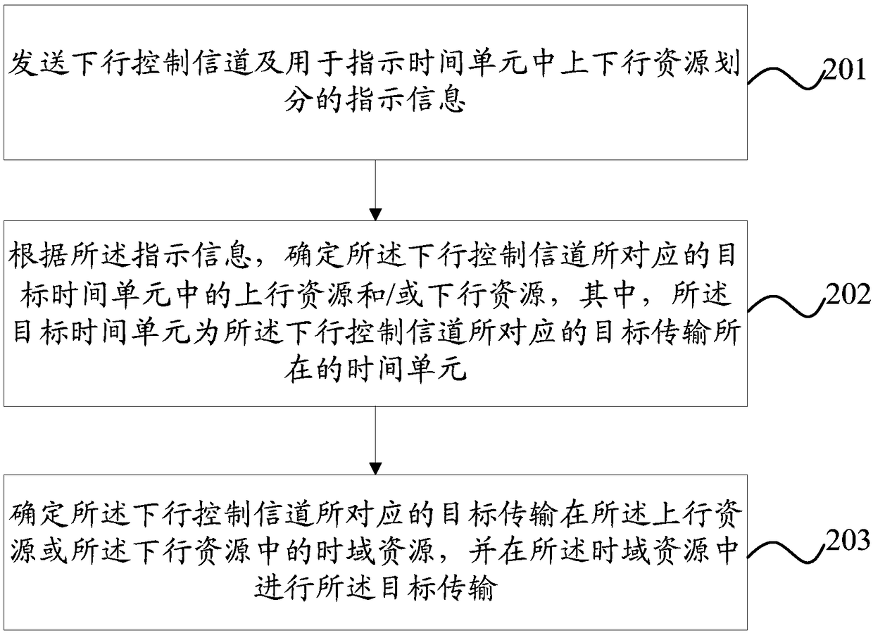
[0192] Such as figure 2 As shown, the embodiment of the present invention also provides a data transmission method applied to a base station, including:
[0193] Step 201: Send a downlink control channel and indication information used to indicate the division of uplink and downlink resources in a time unit.
[0194] In this step, the downlink control channel is the downlink control channel using the uplink DCI format (that is, the downlink control channel that carries the uplink scheduling permission, that is, the uplink scheduling command UL grant) and / or the downlink control channel that uses the downlink DCI format (that is, the downlink control channel that carries the downlink scheduling The permitted downlink control channel, that is, the downlink scheduling instruction DL grant, includes the downlink control channel indicating the release of SPS resources for short downlink semi-persistent scheduling).
[0195] Optionally, the step of sending indication information for indic...
no. 3 example
[0203] This embodiment is a specific application example of the data transmission method of the present invention.
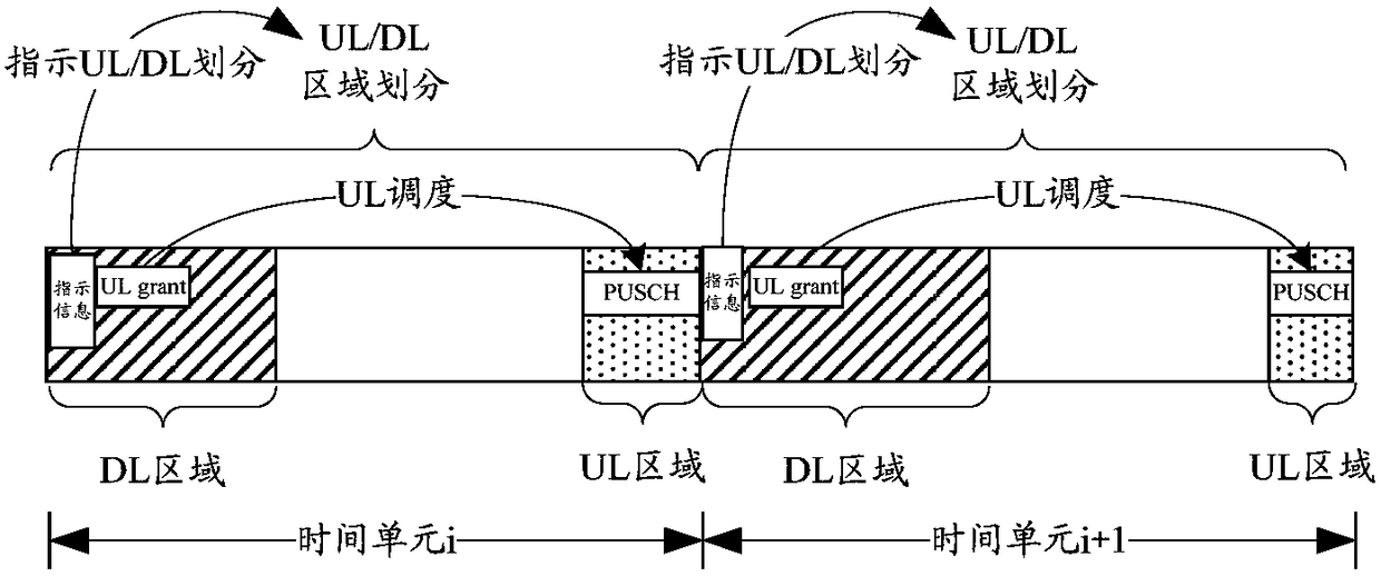
[0204] The embodiment of the present invention takes a slot as a time unit as an example. It is assumed that a slot contains 7 symbols (orthogonal frequency division multiplexing OFDM or single carrier frequency division multiple access SC-FDMA symbols); of course, time units of other lengths are not excluded Way of definition.
[0205] The specific implementation process of the data transmission method in the embodiment of the present invention is as follows.
[0206] It is assumed that the indication information sent at a specific time-frequency position in the current time unit is used to indicate the uplink and downlink area divisions in the current time unit; it is assumed that the UL grant sent in the downlink resource in the current time unit can schedule physical operations in the uplink area of the current time unit Uplink shared channel PUSCH transmission ...
PUM
 Abstract
Description
Claims
Application Information
 - R&D Engineer
- R&D Manager
- IP Professional
- Industry Leading Data Capabilities
- Powerful AI technology
- Patent DNA Extraction
Browse by: Latest US Patents, China's latest patents, Technical Efficacy Thesaurus, Application Domain, Technology Topic, Popular Technical Reports.
© 2024 PatSnap. All rights reserved.Legal|Privacy policy|Modern Slavery Act Transparency Statement|Sitemap|About US| Contact US: help@patsnap.com