Fast mounting mechanism of weaving shaft

A technology of weaving shaft and quick-loading, applied in knitting, warp knitting, textile and papermaking, etc., can solve the problems of high labor intensity, affecting the production efficiency of warp knitting towel machines, slow replacement speed, etc. Dust effect, conducive to continuous weaving, good reliability

Inactive Publication Date: 2018-07-17
ZHEJIANG XINMIAN TEXTILE
View PDF0 Cites 0 Cited by
  • Summary
  • Abstract
  • Description
  • Claims
  • Application Information

AI Technical Summary

Problems solved by technology

During the weaving process of the towel machine, the weaving shaft needs to be replaced and installed. At present, the common weaving shaft replacement and installation are all done manually. The manual labor intensity is high and the replacement speed is slow, which affects the production efficiency of the warp knitting towel machine.

Method used


Image

  • Fast mounting mechanism of weaving shaft
  • Fast mounting mechanism of weaving shaft
  • Fast mounting mechanism of weaving shaft

Examples


Embodiment Construction

[0016] The present invention will be further described in detail below in conjunction with the accompanying drawings and examples. The following examples are explanations of the present invention and the present invention is not limited to the following examples.

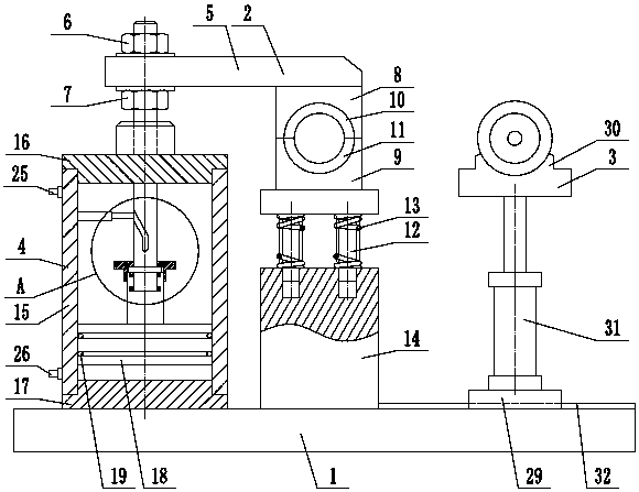
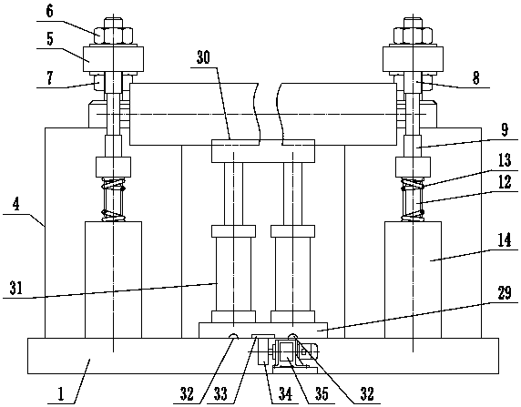
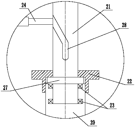
[0017] Such as figure 1 , figure 2 and image 3 As shown, a quick-installation mechanism for weaving beams includes a frame 1, a mounting assembly 2, and a shaft changing assembly 3. The mounting assembly 2 includes a driving cylinder 4, a pressing plate 5, an upper lock nut 6, and a lower lock nut. 7. Upper support seat 8, lower support seat 9, upper semi-cylindrical bearing 10, lower semi-cylindrical bearing 11, ejector rod 12, ejector rod spring 13, fixed support 14, the drive cylinder 4 includes a cylinder body 15, an upper end cover 16. Lower end cover 17, piston 18, sealing dust ring 19, lower piston rod 20, upper piston rod 21, connecting end cover 22, rolling bearing 23, guide pin 24, upper valve port 25,...


PUM


Abstract

The invention provides a fast mounting mechanism of a weaving shaft, and belongs to the technical field of textile machinery. The mechanism comprises a mounting assembly and a shaft changing assembly,wherein a piston of the mounting assembly can be slidably arranged in a cylinder body in a sliding manner, a lower piston rod is coaxially fixed at the upper end of the piston, the lower end of an upper piston rod is slidably connected to the upper end of the lower piston rod, the connecting end cover is in threaded connection with the lower piston rod, and the connecting end cover is attached toa shaft table of the upper piston rod;and a guide pin is fixed in the cylinder body and is inserted into a spiral groove of the upper piston rod, a pressing plate is arranged at the upper end of theupper piston rod, an upper supporting seat is arranged at the lower end of the pressing plate, an upper semi-cylindrical bearing is arranged on the upper supporting base, a lower semi-cylindrical bearing is arranged on a lower supporting seat, a shaft changing support of the shaft changing assembly can be arranged on a guide rail in a sliding mode, a gear and a rack are meshed with each other, thelower end of shaft changing air cylinders are fixed on the shaft changing support, and a weaving shaft bracket is arranged at the upper ends of the shaft changing air cylinders. According to the fastmounting mechanism of the weaving shaft, the weaving shaft can be replaced and installed quickly, the structure is reasonable, and the automation degree is high.

Description

technical field [0001] The invention relates to the technical field of textile machinery, in particular to a quick-loading mechanism for a weaving beam. Background technique [0002] Textile machinery is all kinds of mechanical equipment needed to process natural fibers or chemical fibers into textiles. Although the machinery for producing chemical fibers includes a variety of chemical machinery, it is now considered an extension of textile machinery and belongs to textile machinery in a broad sense. The processes required to process different fibers such as cotton, hemp, silk, wool, etc. into textiles are not the same, and some are completely different, so the machines required are also various and varied. Textile machinery is usually classified according to the production process, including: spinning equipment, weaving equipment, printing and dyeing equipment, finishing equipment, chemical fiber spinning equipment, reeling equipment and non-woven fabric equipment. Spinni...

Claims


Application Information

Patent Timeline
IPC IPC(8): B23P19/027B23P19/00
CPCB23P19/027B23P19/00D04B27/16
Inventor 朱国良
Owner ZHEJIANG XINMIAN TEXTILE
Why Eureka
Try Eureka