Thermal insulation tube clamping lock

A heat preservation pipe and card lock technology, which is applied in the direction of heat preservation, pipe protection through heat insulation, pipe protection, etc., can solve the problems of large randomness, lack of standardization, and increased cost, and achieve easy promotion and popularization of use, appearance Beautiful and tidy, high work efficiency

Inactive Publication Date: 2018-07-17
吴胜利
View PDF0 Cites 1 Cited by
  • Summary
  • Abstract
  • Description
  • Claims
  • Application Information

AI Technical Summary

Problems solved by technology

[0002] The common structure of the connection device of the heat preservation pipe in the prior art is as follows: a galvanized iron box is used to fill the fiber felt. For the individual case of the heat preservation pipe connection, the method is still to use the semi-finished heat preservation material, and adopt manual marking, cutting, corner bending, gripping, etc. The heat preservation methods such as edges, holes, rivets, etc. have achieved certain results, but the materials and paving parts are not standardized, can not meet the standardization, and are one-time use; When replacing, connecting and maintaining the insulation pipe, the iron box and the fiber felt are damaged and need to be remade, which wastes resources and labor twice. The layer is generally directly wrapped on the metal pipe. The defect is that the heat insulation layer is damaged during installation and disassembly maintenance, and a new heat insulation layer needs to be added. The materials and paving parts are not standardized and cannot be standardized. The use increases the cost of maintenance; due to the manual cutting operation, the construction process is random, and it is difficult to guarantee the overall appearance effect

Method used


Image

  • Thermal insulation tube clamping lock
  • Thermal insulation tube clamping lock
  • Thermal insulation tube clamping lock

Examples


specific Embodiment approach

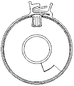
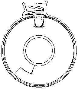
[0023] The insulation pipe latch 10 is injection-molded from high-density polyethylene raw materials, the fixed lock hook 2 and the spring lock hook 1 cooperate, the S-shaped joint groove 4 cooperates with the S-shaped joint convex groove 5, and the interspersed boss 6 and interspersed concave Slot 7 cooperates; the left insulation pipe 11 and the right insulation pipe 12 are butted together and then connected by the insulation pipe lock 10 in the middle; when the decoupling handle 9 is pressed down, the spring lock hook 1 and the fixed lock hook 2 are automatically disengaged, and the insulation pipe lock is completed. The disassembly of the lock: when the left handle 3 and the right handle 8 are firmly pressed along the circumferential direction, the spring lock hook 1 and the fixed lock hook 2 will automatically cooperate to complete the locking of the insulation pipe lock 10.


PUM


Abstract

The invention discloses a thermal insulation pipe clamp lock. The thermal insulation pipe clamp lock is formed by injection molding of a high-density polyethylene raw material, a fixed lock hook (2) is matched with an elastic locking hook (1); an S-shaped joint groove (4) and an S-shaped joint convex groove (5) are matched with each other, and a penetrating lug boss (6) is matched with a penetrating groove (7); a left heat preservation pipe and a right heat preservation pipe are clamped by a heat preservation pipe clamp lock (10) located in the middle of the joint of the left heat preservationpipe (11) and the right heat preservation pipe (12); when an unhooking handle (9) is pressed down, the elastic locking hook (1) and the locking hook (2) automatic disengagement is achieved, and disassembly of the thermal insulation tube clamping lock is completed; and when a left handle and a right handle are forcibly pressed in the circumferential direction, an elastic latch hook (1) and a fixedlatch hook (2) automatic matching is realized, and the locking of the thermal insulation tube clamping lock (10) is completed.

Description

technical field [0001] The invention relates to the technical field of pipeline heat preservation, in particular to heat preservation pipe locks, which can be widely used in thermal power, heating and water supply in the fields of petrochemical industry, electric power metallurgy, textile printing, biopharmaceuticals, marine locomotives, HVAC, etc. Drainage, insulation pipe connection device on refrigeration equipment. Background technique [0002] The common structure of the connection device of the heat preservation pipe in the prior art is as follows: a galvanized iron box is used to fill the fiber felt. For the individual case of the heat preservation pipe connection, the method is still to use the semi-finished heat preservation material, and adopt manual marking, cutting, corner bending, gripping, etc. The heat preservation methods such as edges, holes, rivets, etc. have achieved certain results, but the materials and paving parts are not standardized, can not meet the...

Claims


Application Information

Patent Timeline
IPC IPC(8): F16L59/02
CPCF16L59/024
Inventor 吴胜利苟和平
Owner 吴胜利
Why Eureka
Try Eureka