Auscultation ball type gas pipeline leakage detection device and method

A technology for leak detection device and gas pipeline, applied in pipeline system, gas/liquid distribution and storage, mechanical equipment, etc., can solve problems such as difficult construction, poor application adaptability, and failure in diagnosis, and achieve reliability and robustness Good, high information redundancy, low manufacturing cost

Active Publication Date: 2018-07-17
常州新奥燃气发展有限公司 +1
View PDF6 Cites 6 Cited by
  • Summary
  • Abstract
  • Description
  • Claims
  • Application Information

AI Technical Summary

Problems solved by technology

Summarizing these methods, there are various deficiencies. For example, the sensing cable method needs to be laid together with the pipeline and its test is one-time. The sensor cable should be replaced; the combustible gas sensing method cannot cover all the pipelines to be tested; the disadvantage of the negative pressure wave method is that it has very high requirements for the real-time performance of the diagnosis, that is, the diagnosis system must be able to capture the negative pressure generated when the leak just occurs. Pressure wave signal, otherwise the pressure in the pipeline will reach equilibrium. Although the leakage continues to occur,

Method used


Image

  • Auscultation ball type gas pipeline leakage detection device and method
  • Auscultation ball type gas pipeline leakage detection device and method
  • Auscultation ball type gas pipeline leakage detection device and method

Examples


Embodiment Construction

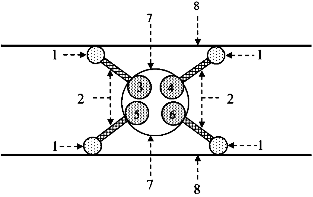
[0033]The present invention will be described in detail in conjunction with accompanying drawing now. This figure is a simplified schematic diagram only illustrating the basic structure of the present invention in a schematic manner, so it only shows the components relevant to the present invention.

[0034] Such as figure 1 As shown, a kind of auscultation ball type gas pipeline leak detection device of the present invention comprises auscultation head 1, sound guide tube 2, auscultation ball 7 and acoustic emission sensor, and in the present embodiment, auscultation head 1, sound guide tube 2 and acoustic emission There are four groups of sensors, or three or more groups. The four acoustic emission sensors are acoustic emission sensor 1#3, acoustic emission sensor 2#4, acoustic emission sensor 3#5 and acoustic emission sensor 4#6, and the acoustic tube 2 is installed on the auscultation head 1 with the same specification. The other end of the acoustic tube 2 is connected t...


PUM


Abstract

The invention provides an auscultation ball type gas pipeline leakage detection device and method. The auscultation ball type gas pipeline leakage detection device comprises auscultation heads, acoustic conducting pipes, acoustic emission sensors and an auscultation ball. Each acoustic conducting pipe is installed on the corresponding auscultation head, and the other end of each acoustic conducting pipe is connected to the corresponding acoustic emission sensor which is located inside the auscultation ball. When the auscultation ball moves along the axis of a detected gas pipeline under the action of the gas flow, the auscultation heads are driven to move along the inner wall of the detected gas pipeline. When gas leakage of the detected pipeline happens, multi-phase turbulent jet flow isformed by fluid in the pipeline on the leaking portion due to the pipe interior and exterior pressure difference of the leaking point, the jet flow, the pipeline and surrounding media conduct interaction with one another to outwards radiate energy, high-frequency stress waves are generated on the pipe wall, picked by the auscultation heads, then amplified by the acoustic conducting pipes and received by the acoustic emission sensors located in the auscultation ball, the change of output signals of the sensors is caused, and finally the output signals of the sensors are integrated to comprehensively evaluate the leakage situation of the gas pipeline.

Description

technical field [0001] The invention relates to the technical field of pipeline leakage detection, in particular to an auscultation ball type gas pipeline leakage detection device and detection method, which are used for qualitative measurement of gas leakage in pipelines. Background technique [0002] After years of research and development, various sensing technologies have been applied to gas pipeline leakage detection, such as metal magnetic flux leakage method, ultrasonic method, combustible gas sensing method, pressure gradient method, negative pressure wave method, flow balance method, sensor Sensing cable method, optical fiber sensing method, etc. Summarizing these methods, there are various deficiencies. For example, the sensing cable method needs to be laid together with the pipeline and its test is one-time. The sensor cable should be replaced; the combustible gas sensing method cannot cover all the pipelines to be tested; the disadvantage of the negative pressur...

Claims


Application Information

Patent Timeline
IPC IPC(8): F17D5/06
CPCF17D5/06
Inventor 季军钟成薛扬陈强谢小中陆贵荣郝永梅
Owner 常州新奥燃气发展有限公司
Why Eureka
Try Eureka