
Special label for cylindrical tubing couplings and mounting method thereof

A label and tubing technology, which is applied in the field of special labels for cylindrical tubing couplings and their installation, can solve the problems of surface corrosion and wear, error-prone, slow recognition speed, etc., to ensure position stability, novel structural design, and prevent falling off Effect

Pending Publication Date: 2018-07-17
东营杰开智能科技有限公司
View PDF1 Cites 2 Cited by
  • Summary
  • Abstract
  • Description
  • Claims
  • Application Information

AI Technical Summary

Problems solved by technology

The oil pipe coupling of this structure has played a role in the downhole operation technology of oil exploitation, but it has the following shortcomings or deficiencies at the same time: ① It is difficult to identify its advantages and disadvantages during use, inspection, repair and management, and it is impossible to detect the service life or The number of times of use is often difficult to prevent due to accidents caused by overdue service; ② There is another kind of marking grooves on the joints, such as oil pipe couplings for fracturing construction. When in use, touch the number of grooves by hand to determine the number of times of use and whether the pipe can continue to be used. The operation of marking grooves and identifying grooves is cumbersome, slow, error-prone, and has a low safety factor; Mark the stamped number on it for identification or etch a marking ring on the outer ring of the oil pipe joint hoop for identification. This identification method can only know the number of times the oil pipe is used, and other detection information such as basic parameters (length, specification, steel grade, etc.) and The maintenance information still cannot be traced; ④ Identify the steel stamp number on the oil pipe, the recognition speed is slow, the accuracy is poor, the recognition efficiency is low, and it is only used to distinguish different types of joint hoops, and it is impossible to achieve fine management of each joint hoop; ⑤ Oil pipe connection After the hoop has been used in the well for a period of time, due to the influence of the downhole oil and water environment, the surface is corroded and worn, and the stamp number is blurred, resulting in large identification errors or even failure to identify
[0003] In order to solve this problem, some existing technologies have developed electronic tags for oil pipe couplings, such as the oil pipe joints with electronic tags in the Chinese patent CN205036312U authorized announcement, including electronic tags and oil pipe couplings, and the electronic tags are installed on the oil pipe On the coupling, and the electronic label includes the shell, the label chip and the buffer material plate, the number of the oil pipe section coupling with the electronic label is easy to read, the built-in information is large, easy to use, easy to identify the number of times it has been used and other required data, but there are still many deficiencies in the use of such oil pipe couplings with electronic tags, such as: (1) The electronic tags and electronic tag holes of this type of device are mostly cylindrical structures, and the electronic tags are fixed to the tag holes by colloid Within a period of time, the electronic tag may fall off due to the influence of the working environment in the oil well after being used for a period of time; (2) The electronic tag of this type of device can only scan the code to read data from the side of the coupling, and does not have Both the top and side of the hoop realize the function of scanning code to read data

Method used


Image

  • Special label for cylindrical tubing couplings and mounting method thereof
  • Special label for cylindrical tubing couplings and mounting method thereof
  • Special label for cylindrical tubing couplings and mounting method thereof

Examples


Embodiment 1

[0030] Example 1 A Special Label for Cylindrical Tubing Couplings

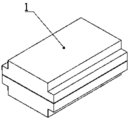
[0031] Such as Figure 1-5 In the shown embodiment 1, a special label for a cylindrical oil pipe coupling includes a label packaging material and label internal components arranged on the substrate mounting surface 2, and the label internal components include a substrate 3, an RFID integrated circuit and a chip 4 and the antenna 5, the internal components of the label are encapsulated into a columnar structure package 6 through injection molding or assembly through packaging materials, the side of the columnar structure package 6 is processed with a plane, and the substrate mounting surface 2 is arranged on the columnar structure package 6, and forms an acute or obtuse angle with the axial direction of the cylindrical structure package 6, the substrate 3 is mounted on the substrate mounting surface 2, and the RFID integrated circuit, the chip 4 and the antenna 5 are deployed on the substrate 3. The oil pipe c...

Embodiment 2

[0033] Example 2 A Special Label for Cylindrical Tubing Couplings

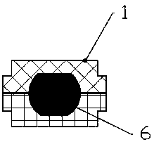
[0034] Such as Figure 6 In the shown embodiment 2, a special label for a cylindrical oil pipe coupling includes a label packaging material and label internal components arranged on the substrate mounting surface 2, and the label internal components include a substrate 3, an RFID integrated circuit and a chip 4 and the antenna 5, the internal components of the label are encapsulated into a columnar structure package 6 through injection molding or assembly through packaging materials, the side of the columnar structure package 6 is processed with a plane, and the substrate mounting surface 2 is arranged on the columnar structure package 6, and forms an acute or obtuse angle with the axial direction of the cylindrical structure package 6, the substrate 3 is mounted on the substrate mounting surface 2, and the RFID integrated circuit, the chip 4 and the antenna 5 are deployed on the substrate 3. The oil pipe cou...

Embodiment 3

[0036] Example 3 A Special Label for Cylindrical Tubing Couplings

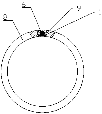
[0037] Such as Figure 7 In the shown embodiment 3, a special label for a cylindrical oil pipe coupling includes a label packaging material and label internal components arranged on the substrate mounting surface 2, and the label internal components include a substrate 3, an RFID integrated circuit and a chip 4 And the antenna 5, the internal components of the tag are encapsulated into a pin-shaped structure package 7 by means of injection molding or assembly as a whole, and the substrate mounting surface 2 is arranged in the middle of the pin-type structure package 7, and is connected to the pin-type structure package 7 The direction of the axis is at an acute or obtuse angle, the substrate 3 is mounted on the substrate mounting surface 2 , and the RFID integrated circuit, the chip 4 and the antenna 5 are arranged on the substrate 3 . The oil pipe coupling 8 for installing the special label is provided with ...


PUM


Abstract

The invention relates to the technical field of petroleum downhole tubing couplings, in particular to a special label for cylindrical tubing couplings and a mounting method thereof. The special labelfor the cylindrical tubing couplings comprises a label encapsulating material and a label internal component disposed on a substrate mounting surface, the label internal component comprises a substrate, an RFID integrated circuit and a chip and an antenna, and the label internal component is integrally packaged into a columnar structure package body or a pin type structure package body with a packaging material in an injection molding or assembly manner. The substrate mounting surface is disposed in a middle portion of the columnar structure package body or the pin structure package body, andforms an acute or obtuse angle with the axial direction of the columnar structure package body or the pin structure package body. The substrate is mounted on the substrate mounting surface, and the RFID integrated circuit and the chip and the antenna are disposed on the substrate. The special label structure for the cylindrical tubing couplings of the invention enhances the stability and safety ofthe label, and realizes reading or writing of the label information in the axial direction and the radial direction of the tubing coupling by the RFID reading and writing device.

Description

technical field [0001] The invention relates to the technical field of downhole oil pipe couplings, in particular to a special label for cylindrical oil pipe couplings and an installation method thereof. Background technique [0002] The structure of traditional downhole tubing couplings is generally a tubular body with female threads at both ends. The oil pipe coupling of this structure has played a role in the downhole operation technology of oil exploitation, but it has the following shortcomings or deficiencies at the same time: ① It is difficult to identify its advantages and disadvantages during use, inspection, repair and management, and it is impossible to detect the service life or The number of times of use is often difficult to prevent due to accidents caused by overdue service; ② There is another kind of marking grooves on the joints, such as oil pipe couplings for fracturing construction. When in use, touch the number of grooves by hand to determine the number ...

Claims


Application Information

Patent Timeline
IPC IPC(8): G06K19/077E21B17/04
CPCG06K19/07724G06K19/07758E21B17/04
Inventor 彭吉友马安彪韩常青
Owner 东营杰开智能科技有限公司
Features
  • Generate Ideas
  • Intellectual Property
  • Life Sciences
  • Materials
  • Tech Scout
  • Unparalleled Data Quality
  • Higher Quality Content
  • 60% Fewer Hallucinations
Learn More